Accuphase P 450 Brochure
This is the 4 pages manual for Accuphase P 450 Brochure.
Read or download the pdf for free.
If you want to contribute, please mail your pdfs to info@audioservicemanuals.com.

Extracted text from Accuphase P 450 Brochure (Ocr-read)
Page 1
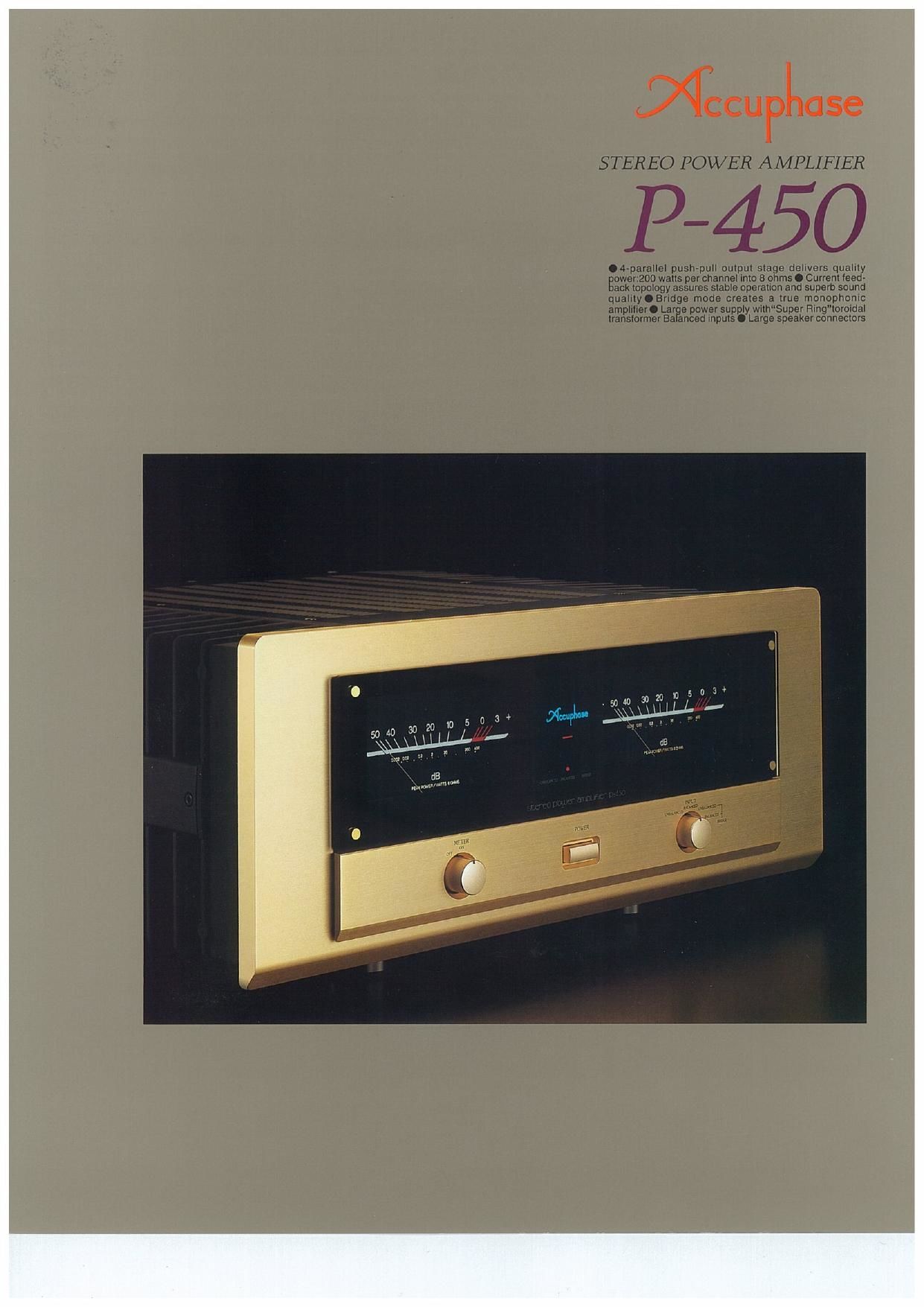
STEREO POWER AMPLIFIER
O 4-paralle1 push»pun output stage delwers quality
Bowenzoo walls per channel into 8 ohms 0 Current teed»
ack topology assures stable operation and superb sound
quality 0 Bridge mode creales a true monophonic
amplllxer. Lar a power supply wi(hSuper angwormdal
translormer Ba anced Inputs. Large speaker connectors
Page 2
The stereo power amplifier P-450 reflects the ex-
tensive knowhow that Accuphase has gained in
building a succession of world-class amplifiers. For
the P-450, all circuit parts and components were
carefully selected for their electrical and sonic per-
formance. This meticulous attention to detail. in
conjunction with features such as the current feed-
back topology developed by Accuphase. ensures
transparent and utterly natural sound that is bound
to captivate the heart of every audiophile and mu-
sic lover.
For faithful music reproduction, a power amplifier
must be able to supply ample energy regardless
of load conditions. This requires a low-impedance
power supply section designed with ample per-
formance margin. The P-450 excels in this regard,
thanks to a highly efficient Super Ring" toroidal
transformer in combination with large filtering ca-
pacitors. In the output stage, newly developed
high-power transistors are used in a 4-parallel
push-pull arrangement. This enables the P-450 to
drive even difficult reactive loads with ease and
authority. A front-panel switch for bridged mode
operation is also provided, which turns the P-450
into a monaural amplifier delivering even higher
output.
The amplifying circuitry of the P-450 features the
Accuphase current feedback principle that has
gained high acclaim the world over. This circuit
combines superb sonic qualities with extraordinary
stability of operation and excellent frequency re-
sponse characteristics. It requires only minimal
phase compensation in the high frequency range,
and response is not affected by gain. NFB can be
kept desirably low, which results in drastically im-
proved transient response.
The massive diecast aluminum heat sinks on both
sides of the amplifier not only look impressive but
are essential to assure stable performance. The
sound of the P-450 is powerful and dynamic, yet
subtle and absolutely true to the musical source.
This new power amplifier makes musical dynamics truly come alive
in your listening room. It combines impressive vigor with high dc-
tail resolution. High acclaimed Accuphase current feedback topol-
ogy guarantees stable operation and great sound even under difficult
conditions. A generously dimensioned power supply and wide-band,
high-performance power transistors connected in a 4-parallc1push-
pull arrangement deliver ample 200 watts into 8 ohms in stereo
operation or 600 watts into 8 ohms when used as a mono amplifier.
Modular Power Units Using 4-Parallel Push-Pull
Configuration Deliver 400 Watts Per Channel
Into 2 Ohms, 400 Watts Into 4 Ohms and 200
Watts Into 3 Ohms
The output stage uses newly developed quality de-
vices with high collector dissipation, excellent fre-
quency characteristics and outstanding reliability.
The transistors are rated for a collector dissipa-
tion of 150 watts and collector current of 15 am-
peres. They also have excellent linearity of
forward-current transfer ratio and outstanding
switching characteristics. The devices are arranged
in a 4-parallel push-pull configuration (see Fig. 1)
and directly mounted on the massive heat sink
made from diecast aluminum. This assures effec-
tive heat dissipa-
tion and yields
impressive out-
put capability on
the order of 400
watts per channel
into two ohms,
300 watts per channel into four ohms and 200
watts into eight ohms. The amplifier can drive even
difficult reactive low-impedance speaker loads with
ease.
Current Feedback Circuit Topology Prevents
Phase Shifts
In order to improve the characteristics of an am-
plifier, a commonly employed technique called
negative feedback (NFB) routes part of the output
signal back to the input. Conventional amplifiers
employ voltage NFB, but the P-450 uses the sig»
nal current rather than the voltage for feedback.
Figure 2 shows the operating principle of this cir-
cuit. At the sensing point of the feedback loop,
current detection with low impedance is per-
formed. A trans-impedance amplifier then converts
the current into a voltage to be used as the feed-
back signal. Since the impedance at the current
, g- sass
new
Fig.1 Circuit Diagram of the Amplifier Unit (one channel)
a.
E
Fig. 2 Current feedback amplifier principle
feedback point (current adder in Fig. 2) is very low,
there is almost no phase shift. Phase compensa-
tion can be kept at a minimum, resulting in excel-
lent transient
re s po n so a n d
natural energy
balance. Figure 3
shows frequency
response for dif-
ferent gain set-
ti n g s of th e _.
current feedback 59.: Frequency responsewilh wmlltedhuk
amplifier. With [responseiemalnsurillormwmvmerigllnchamasl
this circuit, there is virtually no change in frequency
response when gain is altered, and response re-
mains uniform over a wide range.
Bridged Mode Creates True Monophonic Am~
plifier With 800 Watts Into 4 Ohms and 600 Watts
Into 8 Ohms
Bridged mode means that the two channels of an
Av
% SPEAKER
INPUT 9- ' (I %
Signal magnitude
w in doubled.
Fig.4 Principle of Bridge Connection
amplifier are driven with the same signal voltage
but with opposite phase, and their output is com-
bined. The P450 provides a switch arrangement
for bridged operation,
which turns the unit
into a high-grade mon-
aural amplifier capable
of delivering an awe-
some 800 watts into 4
ohms and 600 watts
into 8 ohms.
Switchable bridged
operation mode
Balanced Connection Reliably Blocks Induced
Noise
The P-450 has facilities for true balanced connec-
tion, to shut out any induced noise that could en-
ter the signal path. As shown in Figure 5, balanced
signal transmission means that the output stage
of a component supplies a non-inverted (+) and