Page 1
Output voltage (V)
Output current (A)
Bias stabilizer
circuit
Bias stabilizer
circuit
Bias stabilizer
circuit
Bias stabilizer
circuit
Bias stabilizer
circuit
Bias stabilizer
circuit
Bias stabilizer
circuit
Bias stabilizer
circuitBias stabilizer
circuit Bias stabilizer
circuit
n Two power units, each with an 8-parallel
push-pull arrangement of power MOS-FET
devices, are driven in parallel.
�@ 1-ohm operation possible with music signals only
Figure 2 Load impedance vs. output power (output voltage/output current) Figure 1 Circuit diagram of amplifi er section
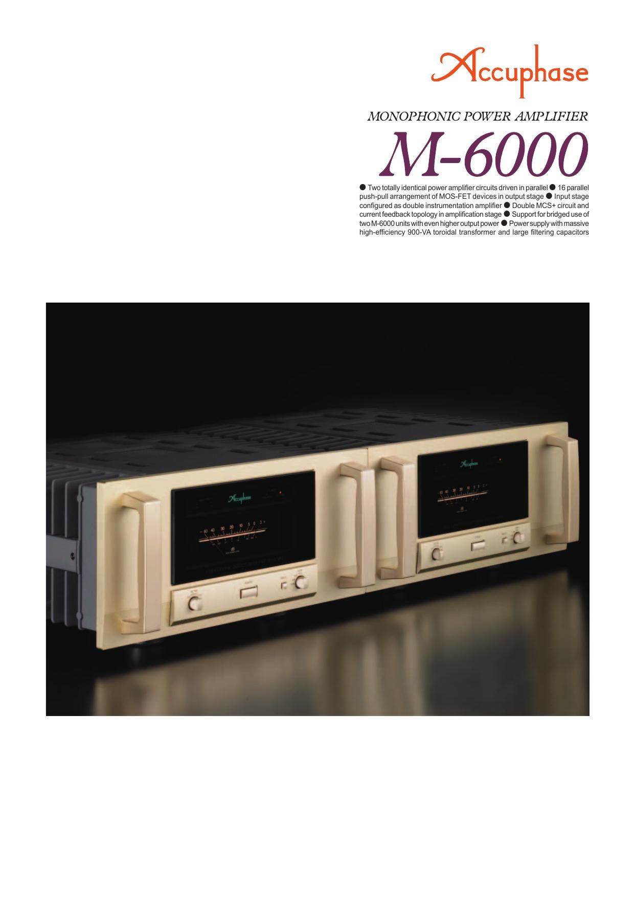
The ultimate power MOS-FET machine -�
This super capable yet astonishingly
nimble monophonic power ampli� er features a double instrumentation ampli� er
setup for fully balanced signal transmission, augmented by a Double MCS+ circuit
and current feedback topology. Experience outstanding sound and drastically
improved performance parameters including excellent S/N ratio and minimal
THD. A hefty power supply and 16 power MOS-FETs arranged in a parallel push-
pull con� guration deliver 1200 watts (music signal) into an ultra-low 1-ohm load.
The M-6000 was born out of a thorough re-evaluation
of the power amplifi er from a new vantage point. Aiming
for nothing less than the ultimate in sound quality, this
monophonic power amplifi er with its massive heat sinks
on both sides stands as an impressive achievement.
The decisive difference to conventional designs lies
in the fact that the M-6000 possesses two completely
identical power amplifi er circuits which are driven in
parallel. Kept entirely separate and mounted on the left
and right sides of the chassis, these circuits deliver output
current reserves on a previously almost unheard-of level.
A damping factor rating of more than 500 demonstrates
that this amplifi er is capable of driving even the most
diffi cult, ultra-low impedance loads with ease.
In a high-output amplifi er, the operating conditions of the
power supply and the thermal conditions can change
dramatically from one moment to the next. To ensure
stable circuit operation under such demanding conditions
must therefore be a top priority. In the M-6000, two
major factors which made driving two power amplifi er
units in parallel possible are the use of power MOS-
FET devices, and the Double MCS+ circuit topology.
Power MOS-FETs are renowned for their excellent
high-frequency characteristics, and they exhibit negative
thermal behavior by design. This makes it easy to control
the temperature balance between two power amplifi er
units, achieving stable operation even when the load and
operating conditions change dramatically. The Double
MCS+ circuit works perfectly together with the current
feedback approach to ensure perfectly controlled phase
characteristics over the entire audible range and even
beyond, extending into the ultra high frequency area. This
results in further improved overall performance. -�� 16-parallel push-pull arrangement of power MOS-
FETs delivers linear power progression: 1200 watts
(music signal) into 1 ohm, 600 watts into 2 ohms, 300
watts into 4 ohms, or 150 watts into 8 ohms.
-�� Strong power supply with large high-effi ciency 900 VA
toroidal transformer and massive fi ltering capacitors
(48,000 μF x 2).
-�� Printed circuit boards made from Teflon with low
dielectric constant and minimum loss.
* Tefl on is a registered trademark of DuPont USA.
-�� Bridged operation of two M-6000 units allows upgrade to monophonic
amplifi er with even higher power, delivering 2400 watts into 2 ohms
(music signal), 1200 watts into 4 ohms, or 600 watts into 8 ohms.
-�� Double MCS+ (Multiple Circuit Summing) topology and current feedback
topology work together for even better S/N ratio.
-�� 4-stage gain selector (MAX,
-�3 dB, -�6 dB, -�12 dB) minimizes residual noise.
-�� Fully balanced circuitry reliably shuts out
external noise.
-�� Phase selector with Normal and Reverse
settings.
-�� Large analog peak-reading meter:
-�� Meter operation and illumination on/off
switch
-�� Switchable peak hold time: 3 seconds or infi nite
-�� Instrumentation amplifi er principle enables fully balanced signal
paths throughout the unit.
-�� Input selector button (balanced/unbalanced) on front panel.
-�� Massive speaker terminals also accept Y lugs.
High-effi ciency toroidal transformer Filtering capacitors
Balanced inputs
Meter circuitry and protection circuitry assembly Gain control selector
Speaker terminal assembly
Page 2
Instrumentation amplifier principle
Signal input stage Power amplifier stage
Principle of current feedback amplifier
Amplifier Output I/V
converter
Current NFB
network Trans-impedance amplifier Current adder
(+) input
buffer (-) input
buffer
The M-6000 employs latest instrumentation amplifi er
topology in a dual confi guration. From the input
terminal right through to the output of the power
stage, the signal is handled only by balanced
amplifi ers. This not only eliminates internal noise and
distortion components, it also makes the amplifi er
extremely resistant to changes in the external
environment, resulting in dramatically improved
stability and reliability.The input stage of the amplifi er section features
another Accuphase innovation. Double MCS+ makes
ample use of cascode drive circuits and dedicates
each component to a clearly defi ned task, thereby
ensuring stable performance. Four circuits for
amplifying the input signal are connected in parallel to
keep distortion to a minimum and to further enhance
S/N ratio and other parameters. The resulting level
of sound quality is simply stunning. As shown in the illustration, the M-6000 uses the output
signal current rather than voltage for feedback. Since
the impedance at the current feedback point is very
low, there is almost no phase shift. A minimal amount
of NFB therefore results in maximum improvement of
circuit parameters.
Double instrumentation amplifi er confi guration
allows fully balanced signal paths throughout Double MCS+ in amplifi er stage further
improves S/N ratioCurrent feedback assures excellent phase
characteristics in high range
Instrumentation amplifi er confi guration and further refi ned Double MCS+ circuit
-�� Power amplifi er assembly with 8-parallel push-pull power
MOS-FET arrangement for output stage mounted directly
to large diecast aluminum heat sink, also comprising MCS+
circuitry and current feedback amplifi er. Two completely
identical circuits are used.