Accuphase G 18 Brochure
This is the 2 pages manual for Accuphase G 18 Brochure.
Read or download the pdf for free.
If you want to contribute, please mail your pdfs to info@audioservicemanuals.com.

Extracted text from Accuphase G 18 Brochure (Ocr-read)
Page 2
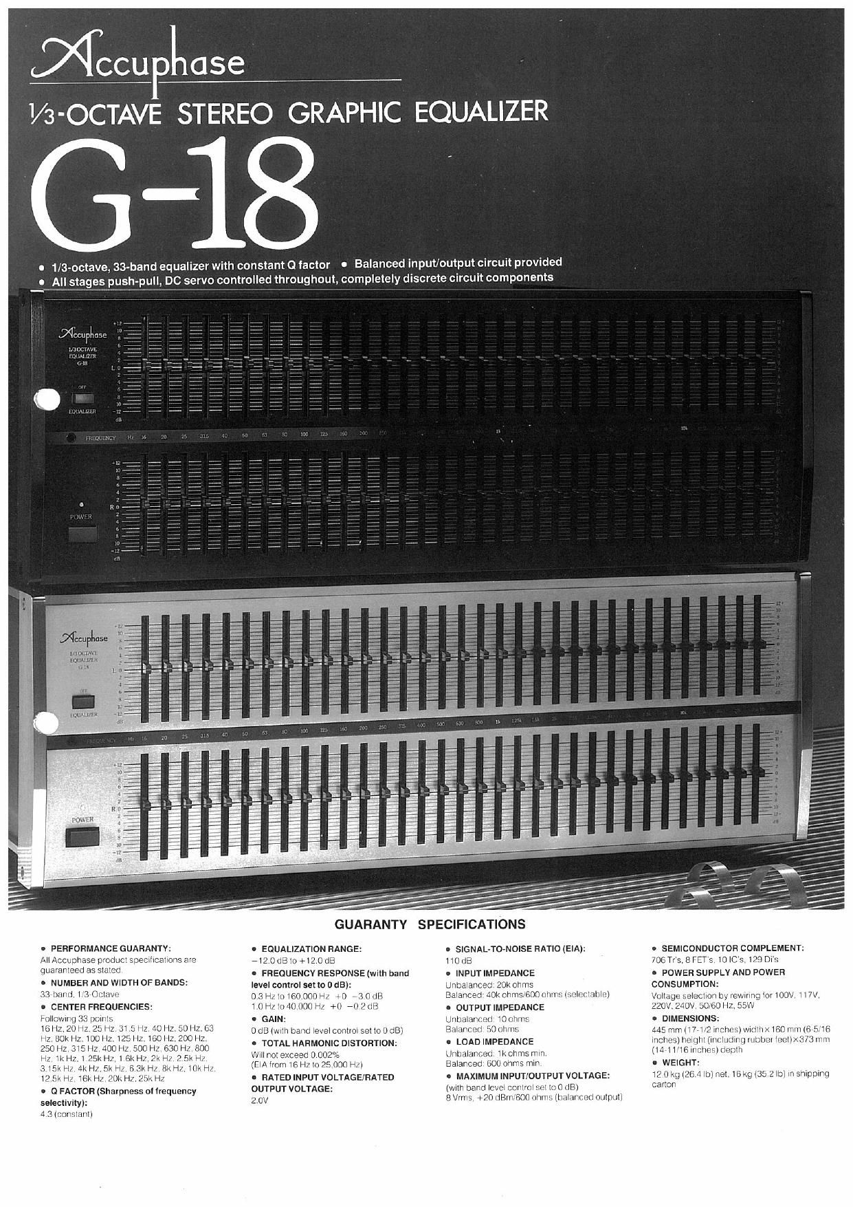
mocupiiase G -18
Stereo Graphic Equalizer
Recent years have seen the increasing popularity oi digital audio sources such as
compact discs, digital recorders, and so on. To reproduce from these sources. fine
tuning of the sound distribution characteristics of the listening room as well as of the
speakers is oi vital importance. The sound distribution characteristic can be smoothed
by compensating for (Le, equalizing) the frequency characteristic of the speakers
Consistent sound quality can be thereby obtained over the entire irequency range,
resulting in a superbly reproduced sound lield with excellent presence and localization
The 6-18 is a 1/3-octave graphic equalizer designed to compensate the sound
distribution characteristic wrthout degrading the sound quality,
One unsolved problem for graphic equalizers had been degradation in the sound
quality, In the development oi the G-18. our special eiiorts tackled this problem. As
their iruil, all the circuits constituting the bandpass iilters are conligured ol discrete
components such as transistors and FETs instead of ICs to improve the overall
characteristic to its upper limit.
The circuit components. including the resistors and capacitors of the bandpass
filters, are painstakingly selected with the criterion oi "improved sound quality", In
addition. the G-1B is so constructed that its left and right channels are independent of
each other. Furthermore, balanced XLFHype connectors are provided as input/output
connectors,
in addition to conventionally employed unbalanced phono-iack
connectors, to prevent degradation of sound quality that may be caused by use or an
extension cable. Thus, the (3-18 is ready for prolessional use also.
Power translormer
Regulated power supply tor lelt channel
(Equalizer board ior the right channel is
located on the bottom or the housing)
Balanced input/output amp
Symmetrical complementary push-pull.
DC servo input amp
Symmetrical complementary push-pull,
DC servo output amp
Symmetrical complementary push-
pull lilter amp group contigured or
discrete circuit components is divided
Into :3 sections (This filter amp group
is tor the left channel: that tor the right
channel Is located on the bottom at
the housing)
1/3-octave, ail-band equalizer
ior correct compensation of
sound distribution
characteristic
Generally, two types oi equalizers are avail
able: the irociave type and the iisroctave
type, Fig. l shows the overall sound distribuV
lion characteristic, including that ol the speakr
ers. at the listening posrtlon at both types or
equalizers, In this llgure, the curves in thin line
indicate the characteristic beiore equalization.
whereas the curves in thick line indicate it alter
As can be seen. the sound distribution
characteristic belore equalization randomly
iluoluates at 30 Hz, 45 HZ, 90 Hz, i30 H2, 160
Hz, 250 Hz, 430 Hz, and so on, namely, at
intervals oi it? to l/3 octave Therelore, with a
l»octave equalizer that equallzes the sound
distribution characteristic on an octave oasis,
namely, equalization based on multiples ol 2
by which the irequency is multiplied. the eilect
IS inadequate though the heaviest iluctuations
can be equalized as shown in Fig, l ta)
Fig, l (bl shows [he sound distribution
characteristic equalized by a t/a-ociave
equalizer As evrdenl, the characteristic is
equalized almost within a range at :3 as.
which is almost Ideal ior practical use. Be
cause oi this design advantage over its couna
terpart. the t/Baoctave equalizer Gala equal-
izes the sound distribution characteristic in the
sound [laid and produces as liat a characteris-
tic curve as possrble
The center frequency oi each band con-
terms to the prelerred irequencies ior acoustic-
al measurements oi ISO (international Stan-
darzation Organization) standard,
The variable frequency range at the G-iB
consists or 33 bands irom to Hz to 25,000 Hz
thereby completely encompassing the audio
band ranging um 20 Hz to 20,000 Hz
Constant 0 lactor to minimize
interlerence between adjacent
bands
The O iactor which determines the sharpness
or each band characteristic is set to 4 3. which
is considered to he a periecl value ior tar
octave equalizers. so that the crossing pornl oi
adlaccnt two bands becomes -3 (18
ll 0 changes with the posrtion oi the level
Conlrol, the interierence between aolacent
bands increases in lnlensliy as shown in Fig, 2
To prevent such increase in interleience the O
iactor ior the Grid IS held constant so that it will
not change with the level control position The
result is the Ideal band characteristic as shown
in Fig, 3
Fig. 2 Fregrioncy cmrecioriaile ol aoau Where 0
Vortuiaoioconl band: or. clgnttlcnnlly aricctch
Fig, 3 Frequency Chuacllriatlc 0164"! Band
wmroo ls Conlllnl to 1.3) (Adi-cent hands
ore hardly stream.)
(a) l-Octlvl Equalizer
to) rid-Octave Equallw
Fig.1 Equallutlnn Examnlol by t- and III-Octave Equlllnu
Bandpass filters consisting of
caretully selected discrete
circuit components
The overall sound quality is determined by the
quality at lhe unii ampirliers constituting the
graphic equalizer such as buliei ampiiiiers and
bandpass tiller amplillers
in ihe case at the GalB. the construction
becomes very Complicated because [he total
number or BPF's is 66 (33 each ior the leil and
the right channels) This complexity in con
slruclroh normally leads to an increase in the
number or circuit components and conse
quenily. mos] graphic equalizers employ opcr
aiional ampllliers lormed by ICs
instead oi lDItDwing surl. however the Gala
employs such discrele circuil components as
transrsicls and FETs ior Substantial improve»
mom 0! the sound quality The bulier ampliiieis
are conligured as dlilerenllal complementary
push pull circuits wrih FET input The band-
pass liller ampliirers are also conirgured as
dilierenlial complementary push-pull circuits
Both the ampliliers realize the topmost per
lcrmance and characteristics The capacrlors
and reststors are responsible tor the quality oi
the bandpass characteristics The capacitors
are especraily important in that they have a
signiilcanl inlluence on the sound quality ol
course. not only these capacrlbrs. but all circuit
components employed in the Gala are chosen
by the most stringent selection methods
possible
Balanced input/output circuit
for excellent sound quality
The longer a cable. the more susceptible the
srgnal is to external noise lransmilled by the
cable
In a balanced cable network, both the
posrlrve and negative signals are generaled
and transmitted between plural pieces oi
equipment. il uhwariied noise is induced dur-
ing the lransmrssioii it is suppressed al the
input circuit Therelore. the signal lransrnllled
by this kind ol network is dillicull to be
adversely atlecled by external noises which
are likely to occur in the Course cl lhe signal
transmission For this reason. the balanced
cable network is employed by many broadr
casting stations as well as by proiessional
audio equipment.
in addition to unbalanced input/output lera
mrnais (phono iacks) conventionally used. the
Gate is provrdeci with balanced XLFiatype
connectors to prevent the sound quality trorn
being degraded by external noise during
transmission. The input impedance oi the Gala
can be changed over between 500 ohms and
40K ohms The buiput impedance is 50 ohms
and thus. the Gala can be connected to a
balanced inpurroutpul signal with any impeV
dance
Two-power supply system and
independent channels
completely eliminating
interference between channels
ii a specriic ireouency band is to be babel-4
(irit up) or attenuated ilili down). interler .
belween the lelt and the right chan
becomes more severe than the iritorlerencc
that may occur with an ordinary ilal amplilrer
The era has an exclusrve litter circuit will
power lianalbrmer coils ior tell and right
channels, each independent oi the other. as an
adequate countermeasure against llilelr
terence
The picture shows the lcll channel oi the
equalizer board The equalizer board tor the
rrghl channel is mounted on lhe bottom bl the
housing. separated by a shielding plate lrom
the lelt channels board
Simple signal route
The GalBiunctions asagraphlc equalizer only,
which means that it does not have inpul/ouiput
terminals tor a tape recorder instead. it has
only one iuncirbnal Switch namely, the
EQUALlZER ON/OFF swrlch to activate or
deactivate the bandpass Iilieis This simplicliy
establishes a Signal rouie through which only a
pure signal is allowed to pass
it IS recommended to insert the (3418 be-
tween the praamplliler and power ampiiirer
Acryl protective panel
attached as accessory V
Exposed level controls may be accidentally
moved irom their set positions Besides, level
controls, some set upward and others down»
ward. are an eyesore For these reasons, a
lranslucent acryl protective panel shields them
trom view
This panel is attached by its pins into the
mating holes on the lront panel oi the 6-18 and
lhereiore attaching or detaching the panel is
easy
Front panel available in two
colors: champagne gold and
black
The color oi the ironl panel is champagne gold.
the traditional colorol Accuphase products As
an alternative, a black iront panel (Type GrieB)
is also available
CCU o 056
ACCUPHASE LABORATORY INC.
1855!
851-0059-00tG1) PRINTED IN JAPAN