Accuphase F 25 Brochure
This is the 4 pages manual for Accuphase F 25 Brochure.
Read or download the pdf for free.
If you want to contribute, please mail your pdfs to info@audioservicemanuals.com.

Extracted text from Accuphase F 25 Brochure (Ocr-read)
Page 1
pawl
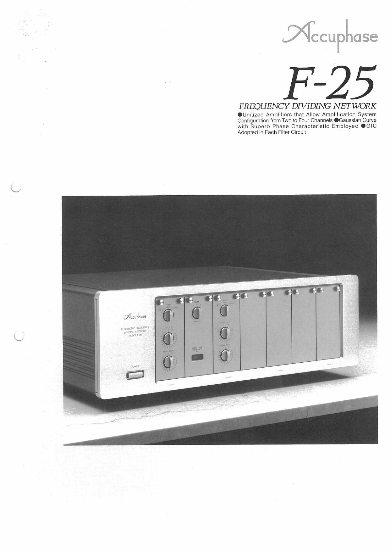
FREQUENCY DI VIDING NETWORK
.Uniiized Amplifiers that Allow Amplification System
Configuiation liom Two to Four Channels .Gausslan Curve
with Superb Phase Characteristic Employed .GIC
Adopted in Each Filter Circuit
Page 2
Ultimate in Audio System Technology - High-Performance Multi-channel
Frequency Dividing Network Equipped with Balanced I/O Circuits and
Serving as the Heart of Multi-amplification System. The Standard Two-
amplification System Can Even be Expanded to a Four-amplification
5 / System through the Addition of Amplifier Units. GIC type Filter Circuitry
A multi»amp|ification system in which the speaker of
each audio frequency range is driven With a dedi-
cated power amplifier has been the most contributing
factor in sound quality improvements by far. offsetting
an inevitable increase in the size of the audio system
Because of its colossal charms as an audio mecha-
nism as well. the multi-amplification system has been
recognized worldwide by many audio enthusiasts as
the ultimate in audio system technology.
Since the unveiling of its first frequency dividing
network F-5 in 1976. Accuphase has been satisfying
the requests of audio enthusiasts with the F-15 and
F-15L. improved versions of the initial product. We at
Accuphase have just completed the development of a
new product F-25 by combining generalized immitv
tance converter (GIC) type filters. adopted for the first
time in any frequency divider. With our balanced trans-
mission circuit technology cultivated over many years.
With the new frequency dividing network in which a
two-amplification system has been adopted as its
basrc system configuration. multi-amplification sys-
tems of up to four channels can be implemented by
simply adding line amplifier units. filler amplifier units.
and crossover boards available as options to the
basic system configuration.
To ensure a better filter curve. the F-25 has
adopted the Gaussian curve that improves the phase
characteristics. As well known. a music signal is a col-
lection of puisive signals Thus. the Gaussian curve
that also improves the impulse characteristics is Ideal
for music signals. With the F25. the attenuation slope
characteristic can be selected with a switch from
among three types: 42 dB/octave. ~18 dB/octave.
and 724 dB/octave.
A generalized immitlance converter (GIC) has
been used in each filter circuit in the multivamplifica-
tion system. The GIC did away with any conventional
filter circuit which can be configured only with induc-
tance (L) and capacitance (C) circuit elements and
has implemented a filter circuit with resrslance (R) and
capacitance circuit elements alone, With the GIC type
filter circuit. an LC tiller circuit can be simulated
wrthout usrng inductance. Moreover, highrprecision
crossover frequency and attenuation characteristics
and Gaussian Curve with Superb Phase Characteristic Adopted in the
Frequency Dividing Network.
can be set by selecting the appropriate circuit con
stants as required.
Another advantage of the GIC is that since signals
in each pass band do not pass through the amplifier.
the purity of these signals can be maintained.
For mounting each Crossover" board which de-
termines the crossover frequency of the network. the
method of dismounting the filter amplifier unit and
mounting the crossover board inside the filter ampli-
fier unit by interconnecting the board and the unit is
employed to prevent deterioration of the sound
quality. as well as to allow interconnections at the
shortest distances. A crossover board is provided for
each frequency. Thanks to the balanced transmission
circuit configuration which Accuphase has been pro-
moting for long for both inputs and outputs. there exits
virtually no difference in the quality of sound between
balanced and unbalanced IIO connections
With all these improvements incorporated in they
F25. you can enjoy sound reproduction of higher
quality than that youve ever hoped to have
unitized Amplifiers tor Amplification System Con-
figuration from Two to Four Channels
With the F-25. filter amplifiers and line amplifiers have
been unitized in such a way that any of these units can
be inserted or removed easily from the front panel of
its housing The basic multi-ampliiication system con-
figuration of the F-25 is a two»arriplification system in
which one filter amplifier unit and two line amplifier
units have been housed as standard equipment.
To upgrade the standard two-amplification system
by increasrng the number of channels. just add ampli-
fier units available as options to the standard equip-
ment as shown in the photos on the right, Fig. 1 shows
a block diagram of the F-25 With a four~amplification
system configuration. Through such unitization of am-
plifiers. Accuphase succeeded in minimizing the
crosstalk between channels
The desired crossover frequency can be selected
lace"
ThrWAmpllfloatlon System Specifications
(with added amplifier units)
Four-amplification System Specifications
(with added amplifier units)
Fig. 1. Block Diagram of Four-amplification System (Indicates the Right or Left channel only.)
'Tvm mm nmpllror unit; and ('10 um amplifier unit: added to the mud-m Two-Amplification System.
by connecting the crossover board of the applicable
frequency to a connector inside the filter amplifier unit
so that the crossover board and the filter amplifier unit
are interconnected at the shortest distance.
Crossover boards are optionally available in 2i
different types to cover crossover frequencies from 70
to 125.000 HZ,
Optional Llne Amplllier
Unit LAZS
Optional Filter Ampllller
Unlt DN-25
Gaussian Curve with Superb Phase Characteristic
Employed as Filter Curve
As the filter curve that divides the frequency. the
Gaussian curve has been adopted. This type of filter
is also used for highrperformance measuring instru
ments such as an FFT analyzer. etc As Compared
With the conventional Bulterworth filter. the Gaussian
curve type has outstanding impulse reproducibility
and thus can faithfully reproduce the original wave-
form
The attenuation slope characteristic of the filter
can be selected with a switch from among three
types: e12dB/octave. vinB/octave. and 724dB/
octave. This characteristic indicates the amount of
attention per octave. The greater the degree. the
greater the amount of attenuation, which improves fre-
quency band separation,
GIC Type Filter circuits
A generalized immitlance converter (GIC) has been
used In each filter circuit that creates cutoff character
istics in the multi-ampfification system, The basic con-
figurations of the GlC type filter are as shown in Fig. 2
(for LPF) and Fig. 3 (for HPF) The GIC did away With
any conventional filler circuit which can be configured
only With inductance (L) and capacitance (C) circuit
elements and has implemented a filter circuit with re,
sistance (R) and capacitance circuit elements alone.
Unlike any conventional feedback type filter circuit.
because signals in each pass band do not pass
through the amplifier. the purity of these signals can