Page 1
n Volume control resolutionAAVA adjusts the listening volume by means of 16 weighted V-I converter amplifi ers
which are controlled by current switches. The number of possible volume steps set by
the combination of these converter amplifi ers is 2 to the power of 16 = 65,536.
n Input buffer amps use 5-MCS topologyOne of the factors that have a bearing on possible noise in an AAVA arrangement
is the input buffer design. By connecting fi ve high-performance amps in parallel,
excellent S/N ratio is assured.
n AAVA maintains high S/N ratio and uniform frequency responseUnlike with conventional volume controls, AAVA does not introduce a change in
impedance at any volume setting. Consequently, there is no deterioration of S/N
ratio, and frequency response remains totally uniform. The benefi ts are especially
apparent at settings that correspond to normal listening levels, because the tonal
quality is not altered in any way.
n No more left/right tracking differences or crosstalkBecause AAVA is an electronic circuit employing fi xed-value resistors, there is virtually
no left/right tracking error also at low volume levels. Since channels can be kept
separate, crosstalk also does not present a problem.
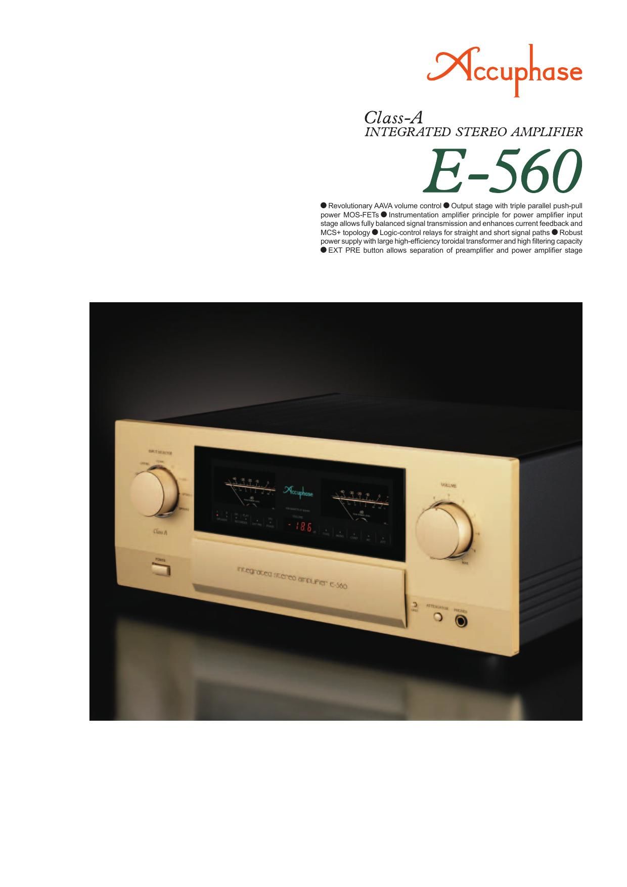
The integrated amplifiers from Accuphase
operating in full class A enjoy an excellent
reputation both in Japan and overseas for
their outstanding musical qualities. The E-560
represents a model change from the popular
E-550. While incorporating the sophisticated
technological know-how gained by Accuphase
over the years, it features a further refined
AAVA volume control and uses the latest cir-
cuit topology and strictly selected parts of the
utmost quality. The E-560 is destined to be-
come the new reference model for high-class
integrated amplifiers.
AAVA is a revolutionary principle designed for
The Ultimate Pure Class A Integrated Amplifi er -� Innovative AAVA volume control
and triple parallel push-pull power MOS-FET arrangement in output stage. Power
amplifi er stage features latest instrumentation amplifi er confi guration for balanced
signal transmission. Current feedback design combined with further improved MCS+
topology results in excellent high-range phase characteristics. Massive power supply
delivers as much as 150 watts per channel (music signal) into loads as low as 1 ohm.
high performance and ultimate sound. It inte-
grates the amplification and volume control
tasks in a single electronic entity that uses
analog processing and eliminates all variable
resistors from the signal path. Its performance
and sonic purity do not deteriorate over the
years, providing excellent reliability. The AAVA
version in the E-560 takes the principle to the
next level, delivering the same peerless per-
formance in a more compact form factor.
The power amplifier section is built as an ad-
vanced instrumentation amplifier, which enables
fully balanced signal transmission throughout.
Together with the further improved MCS+ cir-cuit topology and the highly acclaimed current
feedback principle, this makes for even better
electrical characteristics. In the output stage,
high-power MOS-FET devices renowned for
their great sound and utter reliability are ar-
ranged in a triple parallel push-pull configura-
tion per channel. MOS-FETs have excellent
frequency response and high input impedance
which reduces the load on the preceding driver
stage. They also have perfect thermal stability.
By driving these devices in class A, the ampli-
fier becomes capable of reproducing even the
most delicate details in the music source with
intriguing suppleness and utmost fidelity.
AAVA (Accuphase Analog Vari-gain Amplifi er) Volume Control
AAVA is a radically different volume control principle that eliminates all variable resistors from the signal path and provides top-notch
performance and sound quality. Because the music signal is not affected by changes in impedance, high signal-to-noise ratio and low
distortion are maintained at any volume control setting.
n AAVA means analog processingThe AAVA circuit converts the music signal from a voltage into a current, switches
gain by means of current switches, and then reconverts the current into a voltage.
The entire process is carried out in the analog domain.
n Same operation feel as a conventional high-quality volume controlThe volume control knob position is detected by a dedicated CPU which in turn
selects the current switches for AAVA operation. Operating the knob therefore
feels exactly the same as with a conventional control, and as before, operation
via the remote commander is also possible.
n Attenuator and balance control also implemented by AAVAThe functions of the attenuator and the left/right balance control are covered
by the AAVA circuit as well, eliminating the need for additional circuit stages.
Keeping the confi guration simple helps to maintain high performance and
sonic purity.
n Display shows volume level as numeric valueThe volume level (degree of attenuation) as set with AAVA is shown as a numeric
indication in the center of the front panel. The indication ranges from MAX (0 dB)
to MIN (lowest setting).
The music signal is converted into 16 types
of weighted current by V-I (voltage - current)
converting amplifi ers [1/2, 1/2
2, ... 1/2 15, 1/2 16].
The 16 currents are turned on or off by 16 cur-
rent switches, and the combination of switch
settings determines the overall volume. The
switching operation is controlled by a CPU ac-
cording to the position of the volume control
knob. The combined signal current forms a
variable gain circuit that adjusts the volume.
Finally, the combined current is converted
back into a voltage by an I-V
(current - voltage) converter.
AAVA operation principle
n AAVA volume control assembly
with higher integration density
of components and circuitry. n CPU assembly which controls AAVA and various other
functions.
AAVA confi guration in E-560
INPUT
5-MCS Buffer
Input music signal
Conversion into current with 16
weighting stages (1/2 - 1/2 16)
16 current switches(65,536 possible combinations)
CPU detects position of volume knob and operates
current on/off switches according to knob position
Reconversion of
current into voltage
Current values
are added
Volume knob is turned
and position is detected
OUTPUT
V-I ConverterI-V Converter
CPU Volume
Balance
Attenuator
Page 2
n Power amplifi er assembly and output
stage with triple parallel push-pull power
MOS-FETs directly mounted to large heat sink.
n Supplied remote com-
mander RC-200
Allows volume ad-
justment and input
source switching.
OUTPUT + INPUT
- INPUT
NFB
NETWORK
NFB
NETWORK GAIN CONTROL
CIRCUIT
Bias
stabilizer
Bias
stabilizer
Bias
stabilizer
Bias
stabilizer Multiple Circuit
Summing-up MCS+
Bias
stabilizer
REGULATORREGULATOR
Circuit diagram of E-560 power amplifi er (one channel)
n Power MOS FETs in triple paral-
lel confi guration operating in pure
class A deliver guaranteed linear
power: 120 watts/channel into 2
ohms, 60 watts/channel into 4 ohms
or 30 watts/channel into 8 ohms.
n Instrumentation amplifi er principle
in power amplifi er section allows
fully balanced signal paths. Current
feedback design ensures outstanding high-range phase char-
acteristics, together with further improved MCS+ topology.
n Tone controls using active fi lters for optimum sound quality.
n Dedicated headphone amplifi er optimized
for sound quality.
n Loudness compensator for enhanced bass
at low listening levels.
n Versatile array of inputs with two balanced in-
puts to shut out external noise interference.
n Logic-controlled relays assure high sound
quality and long-term reliability.
n Power supply with massive high-
effi ciency toroidal transformer and
large fi ltering capacitors provides
ample reserves.
n Individual phase setting supported
for each input position.
n Analog peak power meters for
monitoring output levels.
n Two sets of large-size speaker
terminals accept also Y lugs.
n Two option board installation
slots provide further versatil-
ity. With AD-20 board, MC/MM
switching on E-560 front panel is
possible.
n EXT PRE switch and power
amplifi er input connectors allow
independent use of power ampli-
fi er section.
Gold-plated input/output jacks connected directly to relaysPower MOS-FETs
Toroidal power transformer Filtering capacitors
Large speaker terminals