This is the 4 pages manual for Accuphase E 450 Brochure. Read or download the pdf for free.
If you want to contribute, please mail your pdfs to info@audioservicemanuals.com.
Page: 1 / 4
Extracted text from Accuphase E 450 Brochure (Ocr-read)
Page 1
+B3
-�B3
+
-�
-�
+
+B1
-�B1
-�B2
+B2
Q1
Q3
Q2
Q4 Q8
Q6
Q7
Q5 Q9
Q17 Q19
Q18 Q20
Q21
Q22
Q23
Q24
Q13
Q11 Q15
Q10 Q14
Q12 Q16
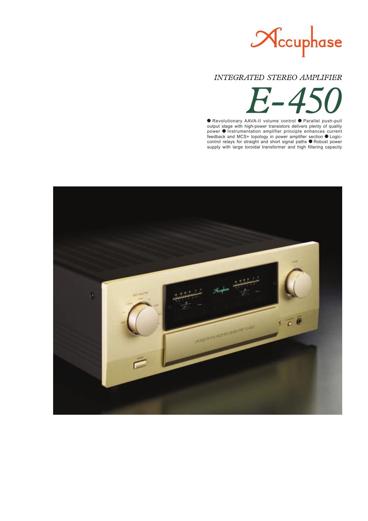
The E-450 succeeds the highly popular and
successful Accuphase model E-408. It refl ects
latest research breakthroughs and features
the innovative AAVA-II volume control princi-
ple. Only top-quality parts are used throughout
its sophisticated circuitry. The overall result is
an integrated amplifi er that brings out even
the most delicate nuances in the music with
breathtaking immediacy.
The AAVA volume control principle developed
by Accuphase totally revolutionizes the way
that the listening volume is adjusted. However,
in its initial form, AAVA required a consider-
able amount of physical space. With AAVA-II,
Accuphase has now taken this principle to the
next level, delivering the same peerless per-
formance in a more compact form factor. This
was made possible by implementing highly
sophisticated surface mount technology while
increasing component density and integration
and optimizing the layout. With AAVA-II, ampli-
fi cation and volume control are fully integrated.
The use of highly reliable electronic compo-
nents eliminates mechanical wear and associ-
ated problems, allowing the control to function
perfectly for many years.
Because an integrated amplifi er has very high
overall gain, even the slightest interference or
crosstalk at the input can have a considerable
effect on the signal provided at the output. To
preclude this possibility, the E-450 is built with
totally separate preamplifi er and power ampli-
fi er sections. Both electrically and structurally,
these two parts operate completely autono-
mously. A set of EXT PRE inputs and outputs
allows using the preamplifi er and power ampli-
fi er separately. In terms of performance quality,
the E-450 can hold its own even when com-
pared with stand-alone components.
The power amplifi er section is built as an
advanced instrumentation amplifi er, which
enables fully balanced signal transmission
throughout. Together with further improved
MCS+ circuit topology and the highly ac-
claimed current feedback principle, this makes
for even better electrical characteristics. In the
output stage, high-power transistors designed
for audio applications are arranged in a parallel
push-pull confi guration, greatly improving the
capability of the amplifi er to drive low imped-
ance loads.
High-class integrated amplifi er with 180 watts per channel (8 ohms) -� Inno-
vative AAVA-II volume control opens up new musical frontiers. High-power
transistors operate in a parallel push-pull arrangement. Power supply with
large, highly effi cient toroidal transformer and oversized fi ltering capacitors
sustains ample power. Instrumentation amplifi er confi guration in power ampli-
fi er makes optimum use of current feedback design combined with further im-
proved MCS+ topology, resulting in excellent high-range phase characteristics.
INPUT
NFB
NETWORK
NFB
NETWORKNFB
NETWORK REGULATOR
REGULATOR
MCS+ (Multiple Circuit Summing-up)
OUTPUT
n Parallel push-pull power amplifi er unit achieves 180 watts
per channel into 8 ohms or 260 watts into 4 ohms.
The output stage devices feature excellent frequency response, current
amplifi cation linearity, and switching characteristics. These high-power
transistors have a rated collector dissipation of 220 watts.
n Instrumentation amplifi er principle in power amplifi er section
allows fully balanced signal paths. Current feedback design
ensures outstanding high-range phase characteristics together with further
improved MCS+ topology.
n Massive high-effi ciency toroidal transformer and large fi ltering capacitor
selected for sound quality provide ample reserves.
n Logic-controlled relays assure high sound quality and long-term reliability.
n Tone controls using active fi lters for optimum sound quality.
n Loudness compensator for enhanced bass at low listening
levels.
n E-450 front panel switching enables MC/MM selection for
optional Analog Disc Input Board AD-20.
n EXT PRE button and preamplifi er output/power amplifi er
input connectors allow independent use of preamplifi er and
power amplifi er sections.
n Dedicated headphone amplifi er delivers audiophile quality
sound.
n Analog peak power meters for monitoring output levels.
n Two sets of large-size speaker terminals.
n High Carbon cast iron insulator feet further enhance sonic
purity.
n Versatile array of inputs with balanced connectors to shut out external
noise interference.
High-power transistors
Toroidal power transformer
Filtering capacitors
Large speaker terminals
Unbalanced input/output jacks and balanced input connectors
High-reliability parts selected for sound quality
Bias
stabilizer
Bias
stabilizer
Bias
stabilizerBias
stabilizer
n Output stage and power amplifi er assembly
with parallel push-pull devices, MCS+ circuit
and current feedback circuitry mounted to
large heat sink Circuit diagram of E-450 power amplifi er
(one channel)
MC/MM Selector
EXT PRE button
Bias
stabilizer
Page 2
+
-�
AAVA-II (Accuphase Analog Vari-gain Amplifi er) type volume control
AAVA-II (Accuphase Analog Vari-gain Amplifi er) is a totally new volume control concept that completely does away with variable resistors in the signal path.
Because the music signal does not have to pass through such devices, there is no adverse infl uence from changes in impedance. This means that the outstanding
S/N ratio and low distortion of the amplifi er are not compromised in any way, and the same superb sound quality will be obtained at any volume setting.
n AAVA-II input stage employs current feedback
principle that ensures high-speed, low-noise
operation and assures excellent characteristics
at high output voltages.
n Volume control resolution.The listening volume is adjusted by a combination of 16 V-I
converters. The number of possible volume steps is 2 to the
power of 16 = 65,536, as determined by current switches.
n AAVA-II circuitry is deceptively simple.Because AAVA-II employs circuitry that is electrically very
simple, long-term reliability is excellent, with performance and sound quality that will remain unchanged also after prolonged
use.
n AAVA-II means analog processing.The AAVA-II circuit converts the music signal from a voltage
into a current, to allow control by current switches, and then
back into a voltage. The entire process is carried out in the
analog domain.
n No more left/right tracking differences or
crosstalk.
Because AAVA-II is an electronic circuit employing only fi xed-value
resistors, there is virtually no left/right tracking error also at low
volume levels, and crosstalk also does not present a problem.
n AAVA-II maintains high S/N ratio and uniform
frequency response.
Because AAVA-II does not introduce any change in impedance,
there is no deterioration of S/N ratio or alteration of frequency
response. Changing the volume with AAVA does not mean
introducing noise or otherwise degrading the sound quality of
the amplifi er.
n Control knob gives same operation feel as with
a conventional high-quality volume control.
n Attenuator and balance control also imple-
mented by AAVA-II.
n Supplied remote commander RC-200
Allows volume adjustment and input
source switching
INPUT
V- I ConverterVolume
Balance
AttenuatorI-V Converter
OUTPUT
Current feedback
amplifi er
Conversion into current
with 16 weighting stages
(1/2~1/2
16)CPU detects position of volume knob
and operates current on/off switches
according to knob position16 current switches
(65,536 possible combinations)
Current
values are
addedReconversion of current
into voltage
Volume knob is turned
and position is detected
CPU
AMP.
FEEDBACK
NETWORK
AAVA-II
operation
principle How AAVA-II works
AAVA-II operates by feeding the music signal to a V-I (volt-
age - current) converting amplifi er where it is weighted in 16
steps [1/2, 1/2
2, ..., 1/2 15, 1/2 16]. The 16 current steps are
turned on or off by 16 current switches, and the combina-
tion of switch settings determines the overall volume. The
switching operation is controlled by a CPU according to the
position of the volume control knob. The combined signal
current forms a variable gain circuit that adjusts the volume.
Finally, the combined current is converted back into a music
signal voltage by an I-V (current - voltage) converter.
n AAVA-II volume control assembly
with higher integration density
of components and
circuitry