Accuphase E 406 V Brochure
This is the 4 pages manual for Accuphase E 406 V Brochure.
Read or download the pdf for free.
If you want to contribute, please mail your pdfs to info@audioservicemanuals.com.

Extracted text from Accuphase E 406 V Brochure (Ocr-read)
Page 1
MECUPIICISG
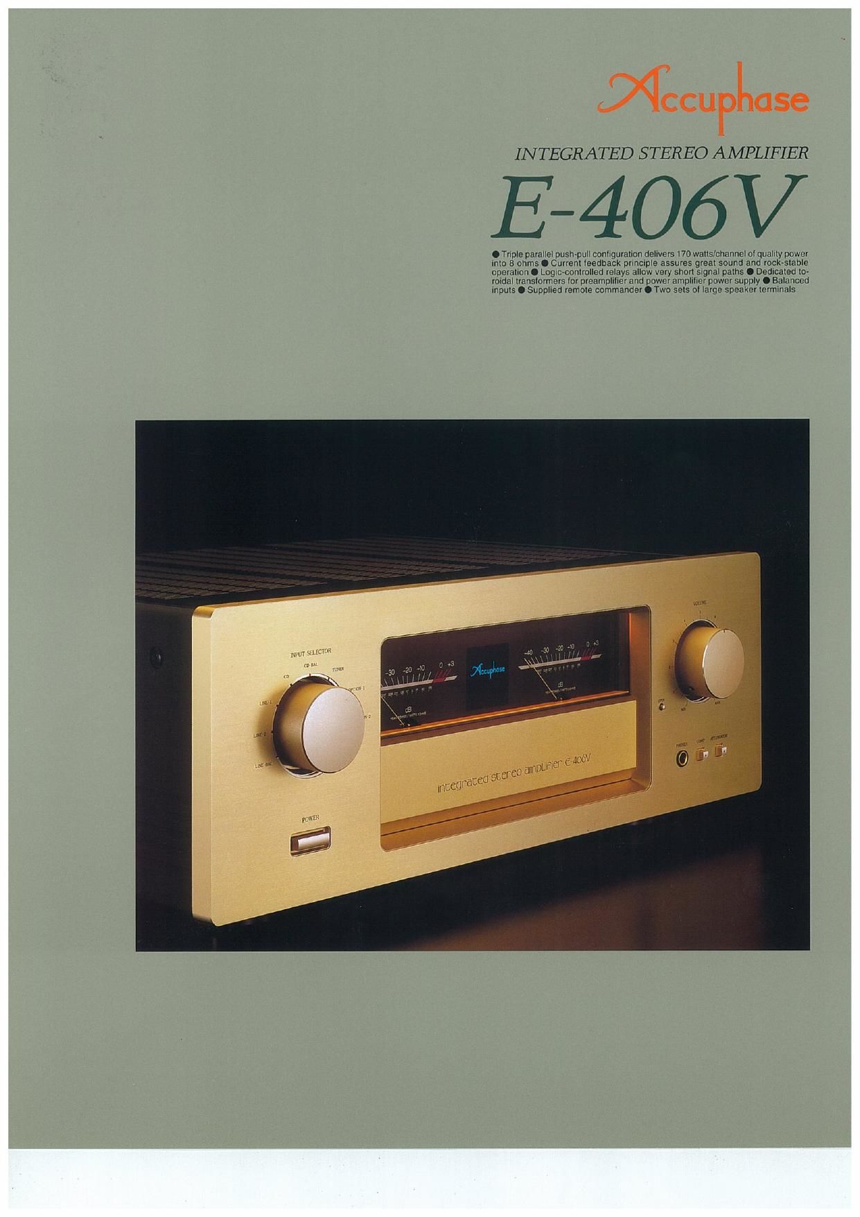
INTEGRATED STEREO AMPLIFIER
E-406V
. Tnple parallel push-pull conllguvallon delrvers l7o walls/channel ol qualrry power
mm 3 ohms o Currenr leermack prmaiple assures gleal sound and rock-arable
operalrorr o Loglc~conlralled relays allow very snun Slgnal palhs o Dedicaled ro-
veldal rranslormers lor preampllllev and power amplrlrer power supply 0 Balanced
mpurs o Supplred remore commander 0 Two 5215 ol large speaker levmlnals
Ltd-l
muff!
Page 2
Based on extensive experience in building superb sepa-
rate-type amplifiers, Accuphase proudly presents the E-
406V. an integrated amplifier destined to become a new
reference. Using only the finest of parts, the E-406V de~
livers sound quality on a truly high level. Dedicated trans-
formers for the preamplifier and power amplifier sections
and carefully designed circuit layout ensure total separa-
tion of these two blocks. A switch even allows using the
preamplifier and power amplifier as independent com
ponents.
Accuphase's highly acclaimed current feedback topol-
ogy virtually eliminates phase shifts in the upper frequency
range and assures uniform frequency response which
does not change With gain. Phase compensation can be
kept at a minimum, and high amounts of negative feed-
back With their associated disadvantages are no longer
required. resulting in excellent transient response, with
superb sonic transparency and detail.
The power amplifier output stage employs a triple paral-
lel pushvpuil configuration, using power transistors de-
signed for high-current audio applications. This improves
drive capability especially with critical low-impedance
loads. The preamplifier section is designed around a cur-
rent feedback line amplifier and is driven by a dedicated
toroidal power transformer which eliminates any possi-
bility of interference from the power amplifier.
A total of eight input positions including two balanced
inputs provide welcome flexibility. including two option
slots on the rear of the amplifier for optional input boards.
Besides a line-level input board, Accuphase offers an
analog disc input board for MM or MC cartridges, allow-
ing reproduction of analog records with outstanding sonic
quality.
The tape enthusiast will welcome provisions for two tape
recorders, with easy dubbing in both directions. Sum-
ming active filter type tone controls and loudness com-
pensation are funher advantages. High-performance logic
relays are used for signal switching, and a supplied re-
mote commander iets the user operate the unit from any
point in the room. The E-AOGV is an integrated amplifier
The new integrated amplifier reference. All signal circuits use cur-
rent feedback topology for superb sound quality and total operation
stability. Ultra-wide-band power tran tors in triple parallel push-
pull configuration provide 170 watts/channel of quality power into 8
ohms. Option boards allow impeccable reproduction of analog discs.
detection is performed. An impedance-converting am-
plifier then converts the current into a voltage to be used
_ _ . _ as the feedback signal. Since the impedance at the cur»
Robust power amplifier section delivers 170 watt per rent feed back
channel into 8 ohms or 220 watts per channel into 4 point (current
ohms _ , adder in Figure 2) W
Figure 1 shows the circuit diagram of the power amplifier is very low. there
section. The power transistors in the output stage are is almost no
high-current devices designed specifically for audio ape p h a s e s h i ft.
plications. They possess optimum frequency response Phase compen-
as well as excellent forward-current transfer ratio linear- sation can be
ity and swrtching performance characteristics. By using kept 0 a mini~ mummy, _
these transistors in a triple parallel push-pull configura- mum, resulting in W- 3 Emmy reswnse Mmcmmymmm
tion, the amplifier is able to handle load fluctuations with (MW Mills me WM" Eflifl Charla)
ease. Operation remains stable at all times, even when
driving reactive low-impedance loads. The rated output
of 170 watts per channel into 3 ohms or 220 watts per
channel into 4 ohms provides more than ample perfor»
mance margin.
with a full complement of features and simply great sound.
cam a
excellent tran-
sient response
and superb sonic transparency. Figure 4 shows frequency
response for different gain settings of the current feed-
back amplifier. The graphs demonstrate that response
remains uniform over a wide range.
Current feedback circuit topology in power amplifier
and line amplifier sections prevents phase shifts
When the gain of an amplifying circuit increases, fre-
quency response, i.e. the bandwidth that can be handled
by the amplifier. becomes narrower. To counter this ef»
feet, a commonly employed technique called negative
feedback (NFB) routes part of the output signal back to
the input. Conventional amplifiers employ voltage NFB, GD
whereby the output voltage is used for the feedback loop,
In the E-406V however, the signal current rather than the
voltage is used for feedback. Figure 2 shows the operat-
ing principle of this circuit. At the sensing point of the INPUT
feedback loop. the impedance is kept low and current a,
Discrete-type line amplifier for superior sonic purity
The line amplifier whose circuit diagram is shown in Fig-
ure 4 is entirely built from discrete parts. to assure opti-
Fig. 4 Line amplifier circuit diagram (one channel)
mum performance. A differential pure complementary
push-pull circuit is used, with an emitter follower output
Fig. 2 Current feedback amplifier principle diagram 5'399- CW5! fEEdbaCk iOPOIOQY further enhances Ch"
cuit operation and reduces the need for phase compen-
sation, resulting in effortless, utterly natural and
transparent sound.
l-Insouu, ,B
0i
lNPtJT
Tone controls use summing active filters for pure
sound
The tone control circuitry in the E-406V was specially de»
signed with summing active filters such as found in high-
quality graphic
> Bum
I
+52
equalizers. Fig-
ure 5 illustrates Inpmw
the operation
Fig. 1 Power amplifier circuit diagram (one channel)
principle of this
circuit. The flat
signal is passed r2
straight through. ffifiifl'
and only when _
an adjustment is Fig. 5 Tone control circuit diagram
required the (summing active filter type)
characteristics are created at F1 and F2 and added to
the signal, thereby producing the desired change, This
design provides efficient control without degrading sig-
nal purity.