Accuphase E 405 Brochure
This is the 6 pages manual for Accuphase E 405 Brochure.
Read or download the pdf for free.
If you want to contribute, please mail your pdfs to info@audioservicemanuals.com.

Extracted text from Accuphase E 405 Brochure (Ocr-read)
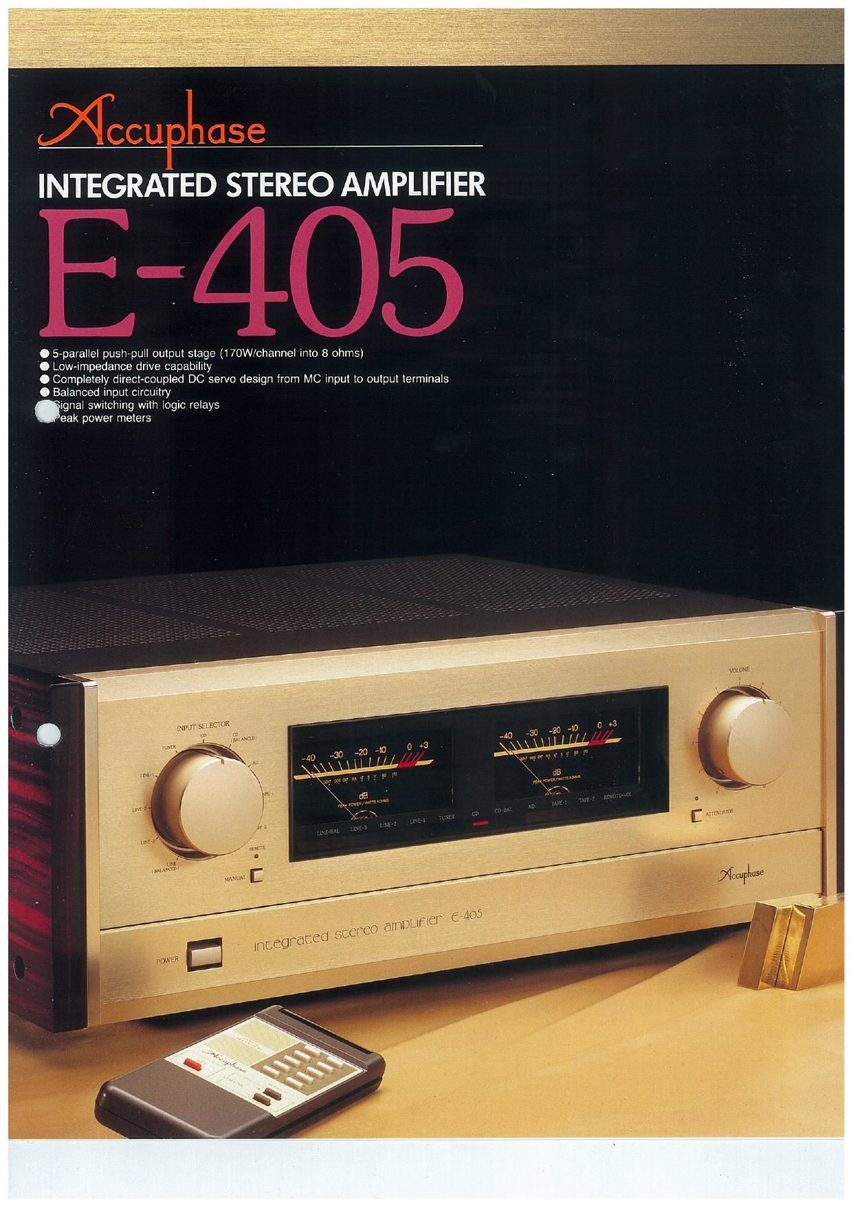
Page 1
O 5-parallel push-pull output stage (WOW/channel into 8 ohms)
O Low~impedance drive capability
0 Completely direct-coupled DC servo design from MC input to output terminals
0 Balanced input circuitry
ignal switching with logic relays
eak power meters
mm sumon
m
Page 2
The overall gain of an integrated amplifier
amounts to as much as 100dB, which srg-
nifies amplification by a factor of 100.000.
Even the slightest interference or noise arisA
ing in the input stage will be magnified man-
ifold and have a detrimental effect on sound
quality. Important advantages of an inte-
grated amplifier are. of course. convenience
and ease of operation. but achieving out-
standing performance is a considerable de-
sign challenge with this amplifier type.
The Accuphase E-405 was designed from
the outset with the goal of advancing the state
of the art in integrated amplifier performance.
To achieve this aim. the amplifier actually
consrsts of a separate preamplifier and pow-
er amplifier section which are housed in a
common enclosure. Even the power transfor-
mers. rectifying circuitry etc. are separate for
the two sections.
In the power amplifier section. five pairs of
transistors are used in a parallel push-pull
configuration. to ensure drastically improved
drive capability. The advantages of this ap~
proach are apparent not only under extreme
low-impedance load conditions. but also
when driving speakers in the 4 to 8 ohm
range. Drive current supply always remains
stable and reliable. unperturbed even by
drastic signal fluctuations. The power am-
plifier stage with its massive power trans-
former. large 33.000uF x 2 filtering cap-
acitors and 170 W/channel rating into 8 ohms
(250 watts/channel into 4 ohms. 350 watts/
channel into 2 ohms) far surpasses the do-
main of conventional integrated amplifiers.
The preamplifier section features the same
design as a high-end stand-alone pream-
plifier. with a 20-dB line amplifier stage and
SOdB (MW/BOOB (MC) phono stage which
are powered by their own power transformer
and rectifiers. Separate stabilizer circuits en-
sure totally uniform current supply and pre-
vent interterence between the respective am»
plifierstagesr Latest digital program sources
as well as traditional analog program sources
can develop their full fascination with this
amplifier.
To accommodate even the most demand-
ing system setup. the E-405 provides a total
of twelve inputs (including two power am-
plifier inputs). Three of these (including one
power amplifier input) are balanced inputs. to
permit signal transmission with ideal charac-
teristics. Facilities for tape recording also
leave nothing to be desired. An independent
recording source selector and a tape copy
switch provide unlimited versatility. Tone
controls employing the summing active filter
principle and a loudness compensator circuit
are designed to provide the required amount
of user control without impairing sound quali-
ty as such
Another important convenience feature of
this amplifier is the supplied remote comman-
der for program source switching and volume
adjustment. The latter uses a motor-driven
design which does not sufferfrom the sound-
quality problems inherent in electronic con-
trols.
The external design of the E-405 stands in
the Accuphase tradition. with a champagne
gold brushed front panel and elegant side
panels made of exquisite persimmons wood.
The front panel layout is simple and un-
cluttered. Two large power meters in the
center are flanked by the input selector sec-
tion and the volume control. Less frequently
used controls are arranged behind a hinged
panel. Overall. sensible human engineering
is in evidence throughout. contributing to the
unsurpassed musical enjoyment afforded by
this amplifier.
POWER AMPLIFIER SECTION
Stage wlth Comblned Maximum Heat
Disslpatlon of 1.300 Watts per
Channel Hellably Drives Low-
Impedance Loads and Delivers
17o watts/channel Into 3 ohms.
250 watts Into 4 ohms. and
350 watts into 2 ohms.
Fig. 1 shows the circuit principle of this am-
plifier's power amplilier section The output
stage consists ot the ten transistors 021 to 030
which are arranged in a parallel push-pull con-
liguration. Each transistor has a maximum heat
dissipation rating (Pc) of 130 watts, resulting in a
combined maximum heat dissipation of 1.300
watts. This is more than ample to drive low»
impedance loads with sufficient power. but it
also contributes to improved linearity when
using speakers with normal impedance charac-
teristics.
The E-405 delivers 170 watts of clean power
per channel into 8 ohms. 250 watts into 4 ohms
(lrom 20 to 20,000 Hz. at O 02% THD). and 350
watts into 2 ohms,
1 Powerful 5-Parallel Push-Pull Output
Casoode Push-Pull 4- M05 FET
Drive Tuned for Perfection
The quality of the drive stage is an important
consideration in a no-compromise amplifier. In
the E-405. as shown in Fig. 1. the transistors 0,2
to 0.5 and 0.710 020 are used to form a direct
dual cascode connection circuit. This principle
guarantees superior linearity up to highest fre-
quencies. and the use of MOS FETs keeps dis-
tortion at low signal levels to an absolute
minimum, The signal voltage used to drive the
output stage is therefore of impeccable duality,
Completely Direct-Coupled
DC Servo Design
All stages of this amplifier. including the pream-
plifier. are linked directly. without any coupling
capacitors in the signal path. This design is ideal
for optimum performance and clean. uncolored
sound. However. as the E-405 also provides
power amplifier inputs. any possibility of DC drift
must be prevented, as this could otherwise lead
to speaker damage.A special DC servo design
developed by Accuphase (ICZ in the center of
Fig. 1) detects any DC component in the outpi -
and feeds it back to the input for cancellatioJ
resulting in zero DC in the final output,
Inputs for Separate Use of the
Power Ampllfier
Separate outputs and inputs controlled by a
selector switch permit use of the preamplifier
section and the power amplifier section as sepa-
rate components. The jacks can also be used to
introduce components such as a graphic
equalizer or a sound processor into the signal
path. The power amplifier input offers a choice
between RCA type phono jacks and balanced
XLFl inputs. (For details on balanced signal con-
necticns. please refer to the paragraph on
preamplifier features.)
Speaker Selector and Large
5 Power Meters
The easy-toread and highly accurate output
power meters in the center of the front panel a)
peak-reading designs. which enables them
precisely follow the rapid changes in amplitude
and frequency that are common with music sig-
nals. A speaker selector employing large.
heavy-duty relays offers switching facilities for
Past
r,
a
9
-nwro-
m3
:3:
:31
Fig. 1 Clrcult dlagram of power ampllflar section