Page 1
+
-�
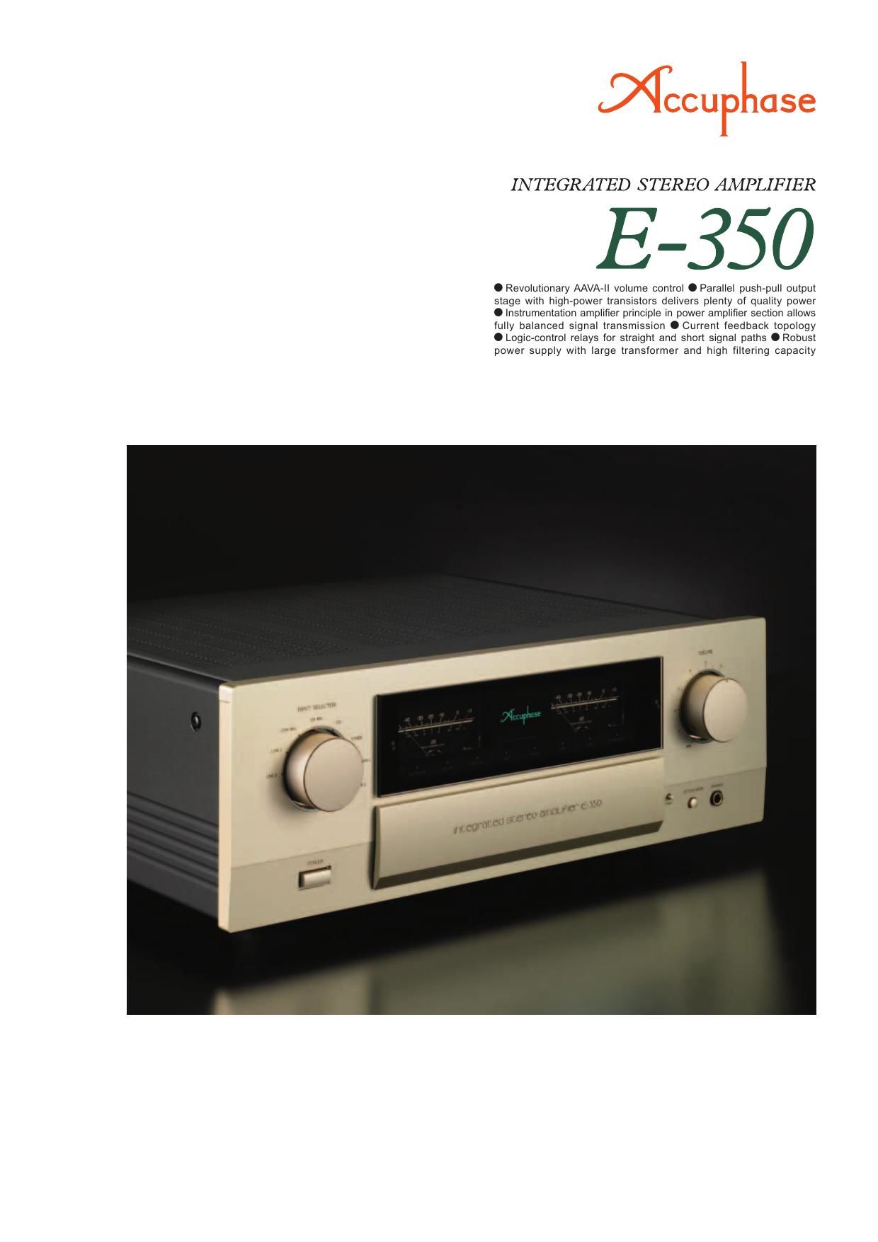
Integrated amplifi er with innovative AAVA-II volume control - Instrumenta-
tion amplifi er confi guration in power amplifi er section allows balanced signal
transmission. Current feedback design ensures optimal high-range character-
istics. High-power transistors in parallel push-pull arrangement are supported
by ample power supply with massive transformer and large fi ltering capacitors.
The result is an abundance of quality power: 100 watts per channel into 8 ohms.
n CPU assembly for control of AAVA-II
and various functions
INPUT
V- I ConverterVolume
Balance
AttenuatorI-V Converter
OUTPUT
CPU
AMP.
Feedback
network
AAVA-II operation principle
AAVA-II (Accuphase Analog Vari-gain Amplifi er) is a novel volume control concept that completely does away with variable resistors in the signal path. Because
the music signal does not have to pass through such devices, there is no adverse infl uence from changes in impedance. This means that the outstanding S/N
ratio and low distortion of the amplifi er are not compromised in any way, and the same superb sound quality will be obtained at any volume setting.
AAVA-II (Accuphase Analog Vari-gain Amplifi er) type volume control
n
AAVA-II input stage employs current
feedback principle that ensures high-speed,
low-noise operation and assures excellent
characteristics at high output voltages.
n Volume control resolutionThe listening volume is adjusted by a combination of
16 V-I converters. The number of possible volume
steps is 2 to the power of 16 = 65,536, as determined
by current switches.
n AAVA-II circuitry is deceptively simpleBecause AAVA-II employs circuitry that is electrically
very simple, long-term reliability is excellent, with
n AAVA-II maintains high S/N ratio and
uniform frequency response
Because AAVA-II does not introduce any change in
impedance, there is no deterioration of S/N ratio or
alteration of frequency response. Changing the volume
with AAVA does not mean introducing noise or otherwise
degrading the sound quality of the amplifi er.
n Control knob gives same operation feel as
with a conventional high-quality volume
control.
n Attenuator and balance control also
implemented by AAVA-II
performance and sound quality that will remain
unchanged also after prolonged use.
n AAVA-II means analog processingThe AAVA-II circuit converts the music signal from
a voltage into a current, to allow control by current
switches, and then back into a voltage. The entire
process is carried out in the analog domain.
n No more left/right tracking differences or
crosstalk
Because AAVA-II is an electronic circuit employing
only fi xed-value resistors, there is virtually no left/right
tracking error also at low volume levels, and crosstalk
also does not present a problem.
The acclaimed E-300 series has a strong following
among discerning music lovers and plays a central
role in the Accuphase integrated amplifier lineup.
Technological excellence is a common theme, and
know-how is inherited and further enhanced throughout
the series. The E-350 represents a full model change
from the model E-308. Featuring the revolutionary
AAVA-II (Accuphase Analog Vari-gain Amplifi er) volume
control, the E-350 combines latest technological
sophistication with high-grade parts and materials,
resulting in an integrated amplifi er capable of bringing
out the fi nest nuances in any music source. The AAVA principle was introduced to high acclaim
in the model E-550, adding another highlight to
the roster of Accuphase audio innovations. The
E-350 now features a further refi ned version of this
revolutionary circuit. While AAVA in its initial form
required a considerable amount of physical space,
AAVA-II delivers the same peerless performance in
a more compact form factor. This was made possible
by implementing highly sophisticated surface mount
technology while increasing component density and
integration as well as optimizing the layout.
The power amplifi er section is confi gured as an advanced instrumentation amplifi er, which enables
fully balanced signal transmission throughout. In
conjunction with the current feedback principle, this
makes for even better electrical characteristics. The
output stage uses high-power transistors designed
for audio applications arranged in a parallel push-pull
confi guration, greatly improving the capability of the
amplifi er to drive low impedance loads. Speaker
operation is sustained by a large power transformer
and amply dimensioned fi ltering capacitors, allowing
the amplifi er to deliver plenty of quality power: 2 × 140
watts into 4 ohms or 2 × 100 watts into 8 ohms.
Current feedback
amplifi er
How AAVA-II works
AAVA-II operates by feeding the music signal
to a V-I (voltage - current) converting amplifi er
where it is weighted in 16 steps [1/2, 1/4, ...,
1/32,768, 1/65,536]. The 16 current steps are
turned on or off by 16 current switches, and
the combination of switch settings determines
the overall volume. The switching operation
is controlled by a CPU according to the
position of the volume control knob. The
combined signal current forms a variable
gain circuit that adjusts the volume. Finally,
the combined current is converted back into
a music signal voltage by an I-V (current-
voltage) converter.
16 current switches
(65,536 possible combinations)
Conversion into current
with 16 weighting stages
(1/2~1/2
16)Volume knob is
turned and position
is detected Reconversion of current
into voltage
Current
values are
added
CPU detects position of volume
knob and operates current
on/off switches according to
knob position
n AAVA-II volume control assembly
with higher integration density of
components and circuitry
Page 2
n Power amplifi er
assembly with
parallel push-pull
devices mounted
to large heat sink and
current feedback circuitry
INPUT NFB
network
NFB
networkNFB
networkOUTPUT
Circuit diagram of E-350 power amplifi er (one channel)
Bias
stabilizer
Bias
stabilizer
Bias
stabilizer
n Output stage is confi gured
with high-power transistors
in parallel push-pull confi gu-
ration, delivering high-quality
power: 140 W/4 ohms or 100
W/8 ohms per channel.
High-power transistors
Large power transformer
Large-size speaker terminals Input/output connectors directly linked to relays MC/MM button
EXT PRE button
n Instrumentation amplifi er principle in power amplifi er section works
in tandem with current feedback design, for outstanding high-range
phase characteristics.
n Logic-controlled relays for signal
switching ensure high sound qual-
ity and long-term reliability.
n Balanced input connectors shut
out external noise interference.
n
High Carbon cast iron insulator
feet further enhance sonic purity.
n Supplied remote
commander RC-200
Allows volume adjust-
ment and input source
switching.
n Power supply features mas-
sive high-effi ciency 550 VA
transformer and two large
fi ltering capacitors (22,000 µF
× 2)
n Analog peak power meters.
n Option board installation
slots.
Filtering capacitors
n Two sets of large-size speaker terminals suitable for Y lugs.
n E-350 front panel switching
enables MC/MM selection for
optional Analog Disc Input
Board AD-20.
n EXT PRE button and pream-
plifi er output/power ampli-
fi er input connectors allow
independent use of pream-
plifi er and power amplifi er
sections.