Accuphase E 306 V Brochure
This is the 4 pages manual for Accuphase E 306 V Brochure.
Read or download the pdf for free.
If you want to contribute, please mail your pdfs to info@audioservicemanuals.com.

Extracted text from Accuphase E 306 V Brochure (Ocr-read)
Page 1
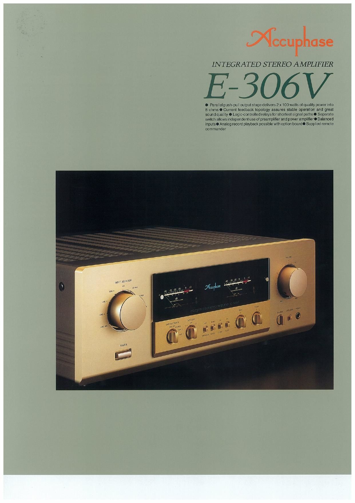
INTEGRATED STEREO AMPLIFIER
E-306V
. Parallel push-pull output stage delivers 2 x 100 watts 01 quality power into
8 ohms . Current leedback topology assures stable operation and great
sound quality . Logic-controlled relays lor shortest signal paths. Separate
switch allows Independent use of preamplifier and power amplilier. Balanced
inputs. Analog record playback possible with option board. Supplied remote
commander
Page 2
Based on the highly successful Accuphase
integrated amplifier E-306. the model E-SOGV is a
further refined and enhanced instrument for totally
faithful music reproduction, It reflects the extensive
experience Accuphase has gained in building superb
separate-type amplifiers. Every single aspect has
been honed to deliver optimum performance.
An integrated amplifier provides various advantages
such as convenient operation and modest space
requirements. However, because its overall gain is
very high. even the slightest interference or crosstalk
at the input can have a considerable effect on the
sonic result. To preclude any possibility of this. the
E-306V is designed to achieve total electrical and
structural separation of the preamplifier and power
amplifier sections.These two parts operate as if they
were entirely separate components. Each has its own
power supply and dedicated regulator circuitry. A
switch even allows using the preamplifierand power
amplifier independently.
Accuphases highly acclaimed current feedback
topology is used in both the preamplifier and power
amplifier.This innovative principle eliminates phase
shifts in the upper frequency range and assures
stable operation and uniform frequency response
which does not change with gain. Phase
compensation can be kept at a minimum. and high
amounts of negative feedback with their associated
disadvantages are no longer required, resulting in
excellent transient response, with superb sonic
transparency and detail.
The power amplifier output stage employs a parallel
push-pull configuration. using power transistors
designed for high-current audio applications. Drive
capability especially with critical low-impedance
loads has been dramatically improved. The
preamplifier section is designed around a current
feedback line amplifier with 20 dB gaint It is driven
by a dedicated toroidal power transformer which
eliminates any possibility of interference from the
power amplifier.
Atotal of seven input positions are provided. including
two balanced inputs for professional- uality noise-
free signal transmission. Flexibility is further
enhanced by an option board slot on the rear of the
amplifier which accepts for example an analog disc
input board for MM or MC cartridges. allowing
reproduction of analog records with outstanding
sonic quality.
The tape enthusiast will welcome connectors for two
tape recorders, with easy dubbing in both directions.
Tone controls. loudness compensation. and a
supplied remote commanderare further advantages.
The newly designed front panel is dominated by the
input selector and volume control knob on both sides.
with large power meters arranged in the center. its
sophisticated design makes the E-SOGV a pleasure
to look at as well as a delight to listen to.
Parallel push-pull output stage delivers
quality power: 140 watts/channel into 4
ohms. 120 watts/channel into 6 ohms or 100
watts/channel into 8 ohms
Figure 1 shows a circuit diagram of the power
amplification stage. The power transistors are
designed for audio applications and have been
selected for optimum
frequency response.
forward-current transfer
ratio linearity. and
switching performance
characteristics The
devices are connected in
parallel and mounted
directly on a large heat
sink for efficient
dissipation of thermal energy This allows the E-306V
to deliver ample power output. amounting to 140 watts
into 4 ohms. 120 watts into 6 ohms. or 100 watts into
8 ohms per channel,
Current feedback circuit topology in power
amplifier and line amplifier sections prevents
phase shifts
When the gain of an amplifying circuit increases.
frequency response. i.e. the bandwidth that can be
handled by the amplifier. becomes more narrow To
counter this effect. a commonly employed technique
Welcome to the world of exhilarating sound. Integrated amplifier with current
feedback topology creates a totally realistic sound stage. Wide-band power
transistors in parallel push-pull configuration deliver 140 watts/channel into 4
ohms, 121) watts/channel into 6 ohms or 100 watts/channel into 8 ohms. Option
board slot allows playback of analog records with impeccable sound quality.
... .......
... -
..-.,...........
.9.
W
M...
Fig. 2 Principle of current feedback amplifier
called negative feedback (NFB) routes part of the
output signal back to the input. Conventional
amplifiers employ voltage NFB. whereby the output
voltage is used for the feedback loop, in the E-306V
however, the signal current rather than the voltage
is used for feedback. Figure 2 shows the operating
principle of this circuit. At the sensing point of the
feedback loop. the impedance is kept low and current
detection is performed. An impedance-converting
amplifier then converts the current into a voltage to
be used as the feedback signal Since the impedance
at the current feedback point (current adder in Figure
2) is very low. there is almost no phase shift. Phase
compensation can be kept to a minimum. resulting
in excellent transient response and superb sonic
transparency, [-~-
Figure 3 showsi
frequency respon-
se for different
gain settings of the
current feedback
amplifier. The
9 r a p h s
demonstrate that
response remains
uniform over a wide range,
ngJFrequsmy responuwith current feedback
iRupmsedoesmtdtangoMiwgainsvaiadL
Discretetype line amplifier for superior sonic
purity
The line amplifier whose circuit diagram is shown in
Figure 4 is entirely built from discrete parts. to assure
optimum performance. A differential pure
complementary push-pull circuit is used, with an
emitter follower output stage, Current feedback
topology further enhances circuit operation and
reduces the need for phase compensation. resulting
in effortless. utterly natural and transparent sound.
oez
oourwr
Fig. 1 Power amplifier circuit diagram (one channel)
.
Fig. 4 Line amplifier circuit diagram (one channel)
Highly reliable logic-controlled relays
Program source switching is performed by logic-
controlled relays which are arranged to permit the
shortest possible signal paths, The hermetically
sealed relays are high-quality types developed
specifically for demanding communication
applications. The contacts are twin crossbar types