Accuphase E 306 Brochure
This is the 4 pages manual for Accuphase E 306 Brochure.
Read or download the pdf for free.
If you want to contribute, please mail your pdfs to info@audioservicemanuals.com.

Extracted text from Accuphase E 306 Brochure (Ocr-read)
Page 1
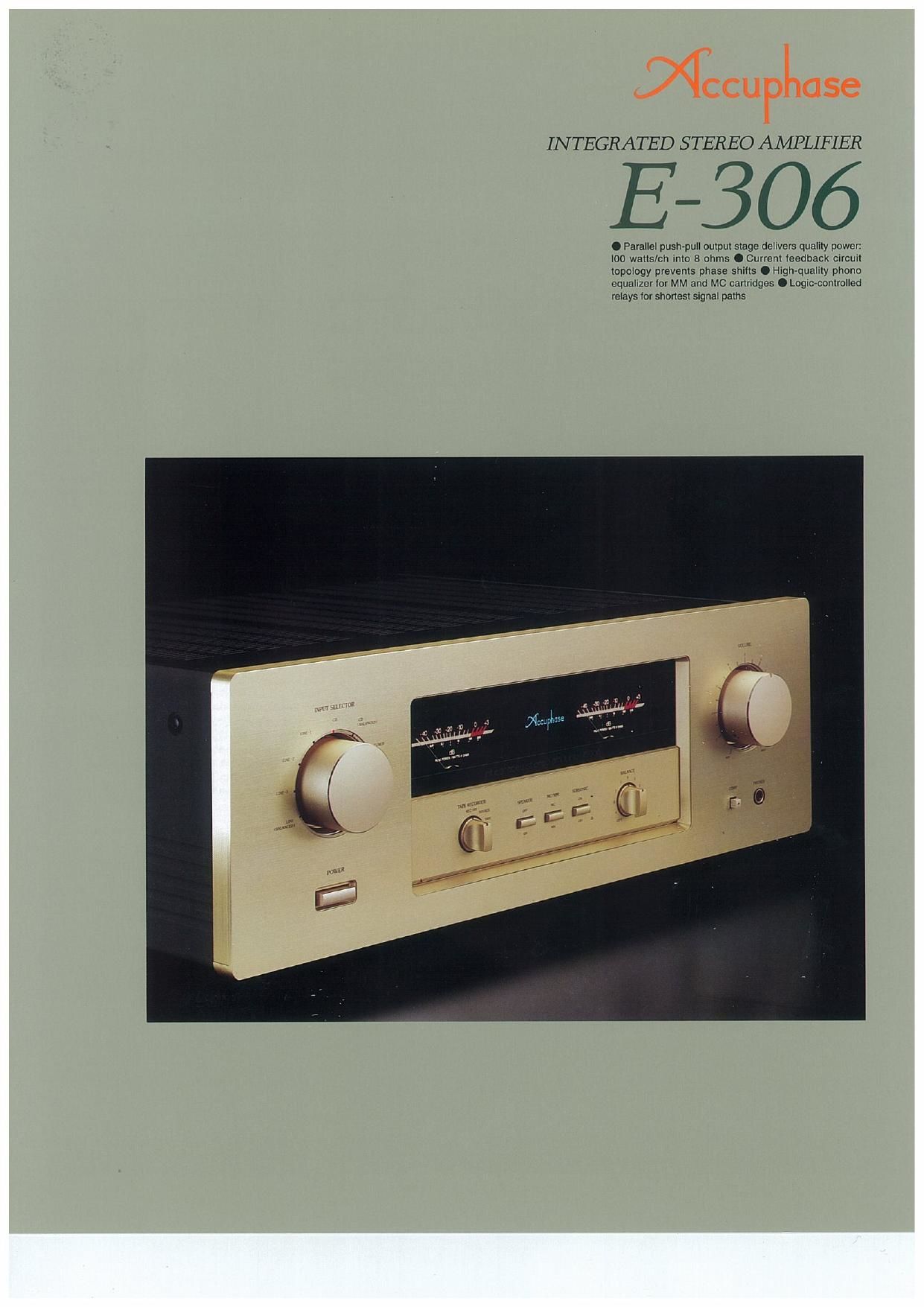
INTEGRATED STEREO AMPLIFIER
E606
0 Parallel push-pull oulpul stage delivers qualily powel:
100 walls/ch Into 8 ohms 0 Current leedback clrcull
topology prevents phase shills O High-quality phono
equalizer 10! MM and MC canridges O Legioconlrolled
relays lor shonesl signal paths
Page 2
An integrated amplifier, as the name implies, com-
bines a preamplifier and a power amplifier in a
single chassis. The preamplifier handles extremely
low-level signals, whereas the power amplifier has
to deal with high currents. This means that overall
gain is extremely high, and even the slightest in-
terference or crosstalk at the input can have a con-
siderable effect on the sonic result. To preclude
this possibility, the E-306 is designed to achieve
total electrical and structural separation of the two
sections. This integrated amplifier opens up a new
chapter in music reproduction, offering sound qual-
ity that rivals some of the best separate compo-
nents.
An important feature of the E-306 is the use of cur-
rent feedback circuit topology in the power ampli-
fier. This principle developed by Accuphase virtually
eliminates phase shifts in the upper frequency
range and assures uniform frequency response
which does not change with gain. In other words. it
combines total operation stability with excellent fre-
quency response. Thanks to this principle. phase
compensation can be kept at a minimum, and high
amounts of negative feedback with their associated
disadvantages are no longer required This assures
excellent transient response, with superb sonic
transparency and detail. Music reproduced by the
E-306 sounds uncannily real.
The preamplifier section incorporates a high-qual-
ity discrete»type line amplifier and a phono equal-
izer for reproduction of analog discs, using MM or
MC cartridges, All parts and circuit components of
the E-306 have been strictly selected for sonic pu-
rity. A versatile complement of nine inputs includ-
ing two balanced inputs can accommodate a wide
variety of program sources. All switching is per-
formed by logic-controlled hermetically sealed reA
lays with gold contacts. A supplied remote
commander lets you adjust the volume and select
input sources from anywhere in the listening room.
In the interest of assuring top»quality sound, the
number of features has been limited to include only
truly essential and useful functions. The simple,
uncluttered design in the Accuphase tradition
makes the 5-306 a joy not only for the ears but for
the eyes as well,
Current feedback circuit topology assures excellent transient re-
sponse and superb sonic realism. parallel push-pull output stage
delivers a full 100 watts/ch of quality power into 8 ohms. High-
performance phono equalizer accommodates MM and MC car-
tridges. Logic-controlled relays assure reliable source switching.
Parallel push-pull output stage delivers quality
power: 140 watts/channel into 4 ohms, 120
watts/channel into 6 ohms or 100 watts/chan-
nel into 8 ohms
Figure 1 shows a circuit diagram of the power am-
plification stage. The power transistors are de-
signed for audio applications and have been
selected for optimum frequency response, forward-
current transfer ratio linearity, and switching per-
formance characteristics. By mounting the devices
to a large heat sink and connecting them in paral-
lel, the E-306 achieves ample power output capa-
bilities, providing a 140 watts into 4 ohms, 120 watts
into 6 ohms. or 100 watts into 8 ohms per channel.
Current feedback circuit topology prevents
phase shifts
When the gain of an amplifying circuit increases,
frequency response, i.e, the bandwidth that can be
handled by the amplifier, becomes more narrow
To counter this ef-
fect, a commonly
employed tech-
nique called nega-
tive feedback
(NFB) routes part
of the output sig-
nal back to the in- __ I
put. If phase shift nu mmmvmrm
is disregarded, a (W W when galn is varied)
circuit designed to have high open-Ioop-gain can
apply a high amount of NFB, resulting in the wide
frequency response of a closed-loop circuit, as
shown in Figure 2.
WE
cum-aw
I-w_l lm
W, l" W
"III-W new
W
I-l
new
Fig. 3 Principle of current feedback unpllfler
Conventional amplifiers employ voltage NFB,
whereby the output voltage is used for the feed-
back loop. In the E-306 however, the signal cur-
{nsggw l... .5,
INPUT
O OUTPUT
_.-��
an) of: on
52
Fig.1 circuit Diagram of the PowerAmplifier Section (one channel)
lnEGuLA-l _a
I run I I
rent rather than the voltage is used for feedback
Figure 3 shows the operating principle of this cir-
cuit. At the sensing point of the feedback loop, the
impedance is kept low and current detection is
performed. An impedance-converting amplitierthen
converts the cur-
rent into a voltage
to be used as the
feedback signal,
Since the imped-
ance at the cur-
rent feedback
point (current _.
adder in Fig. 3) is mdfimmmmmtlumk
very low, there is Wmmmmofln llvmW
almost no phase shift. Phase compensation there-
fore can be kept to a minimum, resulting in excel-
lent transient response and superb sonic
transparency. Figure 4 shows frequency response
for different gain settings of the current feedback
amplifier, The graphs demonstrate that response
remains uniform over a wide range.
Robust power supply
with large power
transformer and high
filtering capacity
The power supply plays
a vital role as the source
of energy for the power
amplifier section. The E-
306 spares no efforts in
this regard, featuring a
large 500 VA power
transformer and two
large electrolytic capaci-
tors rated for 22,000 pF
each. This assures
ample reserves also for
reproduction of de-
manding bass pas-
sages.
Discrete-type line amplifier for superior sonic
purity
The line amplifier whose circuit diagram is shown
in Figure 5 is entirely built from discrete parts, to
assure optimum performance. Circuit design is
based on the differential pure complementary push-
o .5
(I) 05 or
Input {i ( D]
at as
ooutput
a: o4
(P ° °
o-B
Fig.5 Circuit Diagram of the Line Amplifier (one channel)
pull principle developed by Accuphase, while the
output stage is a single-ended push-pull emitter
follower. This comparatively simple circuit topology
requires only minimal amounts of phase compen-
sation in each stage, which enhances signal purity
and results in effortless, utterly natural sound.