Accuphase E 303 X Brochure
This is the 4 pages manual for Accuphase E 303 X Brochure.
Read or download the pdf for free.
If you want to contribute, please mail your pdfs to info@audioservicemanuals.com.

Extracted text from Accuphase E 303 X Brochure (Ocr-read)
Page 1
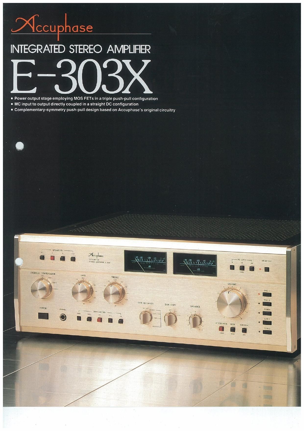
INTEGRATED STEREO AMPLIFIER
-303)(
0 Power output stage employing MOS FETs in a triple push-pull configuration
I MC input to output directly coupled in a straight DC configuration
0 Complementary-symmetry push-pull design based on Accuphases original circuitry
:- hm mm E
'I I I I 5 "mu'i",,';°,,,;;
imimnss coMFuIS/uou
m ms m l
,J
\\\
W, mm
m ,uww
Page 2
All-stage push-pull circuitry. All signal paths directly coupi
MOS FETs in a triple push-pull configuration can drive eve
@
Fig. 1 Circuit Diagram of Power Amplifier
Though an integrated amplifier, the E-303X
incorporates much of the sophisticated technology
and quality circuit components originally de
veloped for use in Accuphases separate am-
plifiers, Its resulting high-level performance per-
mits the E-303X to handle even purely digital audio
sources. such as Pulse Code Modulation (PCM)
recordings and Compact Discs.
The power output stage of the E7303X uses
high-speed MOS FETs in a triple push-pull cone
figuration to deliver one of the highest outputs of
any integrated amplifier: 150 watts per channel
(into 8 ohms. from 2040.000 Hz. with no more
than 0.01% THD). This means the E-303X has
more than enough power to drive even low
impedance loads. Forexample. output into 2 ohms
is an enormous 250 watts per channel.
The circuitry is based on Accuphases original
complementary~symmetrical push-pull design and
generous employment of the cascode push-pull
configuration realizes ideal high-frequency char-
acteristics. This design raises overall performance
to the highest level possible Funhermore. all
amplification stages from MC (Moving Coil Car-
tridge) input to output are directly coupled in a
straight DC (capacitorless) configuration to pro-
vide amplification with a minimum of coloration.
The E-303X also has an input impedance
selector to assure optimum performance With all
sorts of MC cartridges Other features include tone
controls automatic loudness compensation for
listening at low-volume levels. abundant facilities
for tape decks. and a complete range of input
terminals to accommodate even large. multi-
component audio systems Inside and out. the
E-SOGX is fully equipped to meet the increasingly
complex needs of todays high quality audio
components
output stage delivers 150 watts of
clean power per channel.
The power output stage employs a triple push-pull
configuration using six MOS FETs having a gener-
ous PD (maximum power dissipation) of 600 watts.
MOS FETs have already been used in a great
number of Accuphase power amplifiers where
they have gained a solid reputation for their sonic
purity. For your reference. the main advantages of
MOS FETs are described later,
The circuit diagram for the power amp section
is shown in Figure 1. As you can see. the design is
clean and allows easy operation. The preliminary
stage is a differential push»pull circuit consisting of
tranststcrs 02 and 03. Next comes a cascode
push»pull circuit with transistors 06709. and the
MOS FETs 012-017 are driven by the 010 and
Off pre-drivers. In this circuit design, the most
important point affecting performance is the case
code push-pull circuits respectively composed of
06 and 08. and Q7 and 09
The cascode configuration is most often used
in the radio frequency amplifier circuits of tuners
because this type of circuit is not plagued by the
Miller effect even when handling high frequencies.
Along with the cascodes high gain. this makes a
significant contribution to improving performance
in all power amp stages.
1 Triple push-pull MOS FET power
' 3 .. at: or
Fig. 2 Circuit Diagram of Equalizer Ampllfter
Large power supply and powerful
output stage drive even 2-ohm
speakers with ease.
The nominal impedance of a speaker is nothing
more than a representative value obtained at a
specific frequency. The actual impedance fluctur
ates a lot across the speakers frequency range.
Consequently. the actual impedance of a speaker
system having a nominal impedance'of 4 ohms
may drop to as low as 3 ohms or even 2 ohms for
some frequency ranges. Impedance can also drop
momentarily when cenain kinds of transient Slg
rials are reproduced. Because of this. only an
amplifier capable of handling these low imped-
ances can drive a speaker system accurately.
A directly coupled solid-state amplifier gener-
ates increasingly large currents in proportion to
decreases of the load impedance. which can
result in destruction of output elements. Because
amplifier output in general can handle currents
only up to a certain strength. some sort of
protection circuitry must be provided to prevent
currents above a certain level from reaching the
outputs (and speaker). As a result. the maximum
output level for low impedance loads is severely
restricted with these amplifiers.
On the other hand. the power amp section of
the E-303X has a high power output stage and a
generous power supply section to supply very
high outputs safely when necessary. As a result,
the E-303X can be connected to low impedance
speakers, Into 2 ohms. for example. the E-303X
can output an awesome 250 watts per channel.
Dlrectly coupled circuitry with DC
servo preserves MC signal purity
from input to output.
The E«303X employs a virtually ideal configuration
in which the MC head amp. equalizer amp.
high
original signal is amplified and output in a virtually
unaltered state to provide an extremely high level
of fidelity. To eliminate DC drift completely. a
problem that exists in all directly coupled amps. a
powerful DC servo is used to stabilize each unit
amp.
til-channel power MOS FETs
NPN pre-drive transistor
Primary stage complementary single-chip dual transistor
... a. Haw
Flg. 3 Circuit Diagram at Head Amplifier
All-stage push-pull EQ amp with
differential amplifier input,
cascode pre-drive, and Darlington
pair output.
Disc sound quality largely depends on the equaliz-
er (EQ) amp. because the EQ amp determines
RIAA characteristics. The circuit diagram of the
E-303Xs E0 amp is shown in Figure 2. The input
stage is a differential amplifier with an FET buffer.
the pre-drive stage is a cascode circuit composed
of 097012. and final stage is a Darlington rfair
output composed of 013-016. Each stag >l
ploys push-pull circuitry.
The pre-drive stage cascode connection con
sists of two pairs of transistors. 09 and Oil. and
010 and 012. respectively. As stated in Section 1
describing the power amp. these cascode con-
nections have excellent high»trequency character-
istics to offer stable. low-distortion performance
over a wide frequency range
The Darlington pair output is also composed of
two pairs of transistors. Q13 and 015. and OM
and 016. respectively. Because the input imped-
ance of this stage can be raised to a value
multiplied by the hFE (static forward current trans-
fer ratio) of 013 and 014. pre-drive stage perform»
ance is not easrly affected by the load. This makes
possible the creation of an amp haying low
distortion and excellent stability.
In this manner. Accuphase has put together a
series of outstanding indiVidual circuits in a com»
pletely push-pull configuration to raise amplifier
performance to the highest level possible before
adding negative feedback and to obtain the pure
quality sound.
Power supplies are provided by constant vol-
tage power supplies on each printed circuit board
to reinforce operation further. J
i
U Head Amplitier/
Equalizer Amplifier
Circuit Board
NPN drive transistor
Output relay for speaker A
DC servo circuit
0 Power Amplifier Unit
Input stage singlechip FET
PNF pie-drive transistor
P-chennel power
MOS FETs
PNP drive transistor
Output relay tor speaker B