This is the 4 pages manual for Accuphase E 250 Brochure. Read or download the pdf for free.
If you want to contribute, please mail your pdfs to info@audioservicemanuals.com.
Page: 1 / 4
Extracted text from Accuphase E 250 Brochure (Ocr-read)
Page 1
+ B3
- B3
+ -
+ B2
- B2
- B1
+ B1
Q 1
Q 2 Q 4
Q 3
Q 5
Q 9
Q 10
Q 11
Q 12
Q 13
Q 14
Q 7
Q 6
Q 8
+ -
10 100 1k 10k 100k
18
16
14
12
10
8
6
4
2
0
2
4-
- -6
Unbalanced input/output jacks and balanced input connectors
n Parallel push-pull power ampli fi er unit achieves 115 watts
per channel into 4 ohms or 90 watts into 8 ohms.
The output stage devices feature excellent frequency response,
current ampli fi cation linearity, and switching characteristics. These
high-power transistors have a rated collector dissipation of 100
watts.
n Instrumentation amplifier principle in power
ampli fi er section
This allows the con fi guration of fully balanced signal paths
from the input jacks to the output stage, including the
signal input stage. In addition, the current feedback design
ensures outstanding high-range phase characteristics.
n Large and highly ef fi cient 400 VA transformer and
two 22,000 μF fi ltering capacitors selected for
sound quality provide ample reserves.
n Option board installation slot provides further
versatility. With AD-20 board, MC/MM switching on
E-250 front panel is possible.
n EXT PRE switch and power ampli fi er input connectors allow
independent use of power ampli fi er section.
n Use of metal thin- fi lm resistors in all signal paths ensures
superb low-noise performance.
n Large analog power meters show direct power output
levels.
n Logic-controlled relays for signal switching ensure high
sound quality and long-term reliability.
n Loudness compensator for enhanced bass at low listening
levels
n High Carbon cast iron insulator feet further enhance sonic
purity.
n Versatile array of inputs with balanced connectors to shut out
external noise interference.
n Two sets of large-size speaker terminals designed for
Y lugs.
The Accuphase E-200 series of basic integrated
ampli
fi ers enjoys an excellent reputation both in
Japan and on the international stage. The E-250
represents a full model change of the E-213,
featuring the new AAVA-II volume control and
re fl ecting the latest design technology advances
achieved by Accuphase. Carefully selected high-
quality materials and parts are used throughout,
in order to bring out even the fi nest nuances of
the source. Using this integrated ampli fi er af-
fords pure musical enjoyment.
In the category of integrated ampli fi ers, AAVA
implemented in the E-550 and AAVA-II in the
E-450 and E-350 have received high praise for
being a clearly superior volume control princi-
ple. The E-250 inherits this advanced design
technology. In order to fi t within the more limited
space available, circuitry and component layout
have been further re fi ned and advanced integra-
tion technology is used to increase mounting
density. This was achieved while retaining the
outstanding performance that made AAVA and
previous AAVA-II implementations such impres-
sive feats of technology. AAVA-II in the E-250
of course also completely eliminates variable
resistors from the signal path. Ampli fi cation and
volume control are integrated in a single entity
consisting only of top-quality and highly reliable
semiconductor parts. This eliminates mechani-
cal wear and associated problems, allowing the
control to function perfectly for many years.
The power ampli fi er section is con fi gured as
an advanced instrumentation ampli fi er, which
enables fully balanced signal transmission
throughout. In conjunction with the current
feedback principle, this makes for even better
electrical characteristics. The output stage uses
high-power transistors designed for audio ap-
plications arranged in a parallel push-pull con-
fi guration, greatly improving the capability of the
ampli fi er to drive low impedance loads. Speaker
operation is sustained by a large power trans-
former with a maximum rating of 400 VA and
amply dimensioned fi ltering capacitors, allowing
the ampli fi er to deliver plenty of quality power:
2 × 115 watts into 4 ohms or 2 × 90 watts into
8 ohms. Power ampli fi er inputs and an EXT PRE
function let you use the power ampli fi er sepa-
rately in a stand-alone con fi guration.
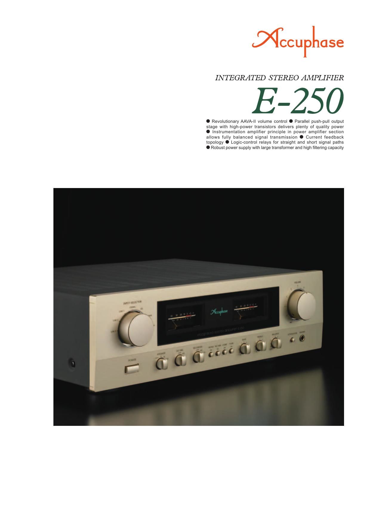
Integrated amplifi er with innovative AAVA-II volume control -� In the power am-
plifi er stage, high-power transistors in a parallel push-pull arrangement are\
sup-
ported by a power supply with massive transformer and large fi ltering capacitors.
Experience 90 watts per channel (into 8 ohms) of quality power before \
a perfectly
silent background. Instrumentation amplifi er confi guration allows balanced signal
transmission. Current feedback design ensures optimal high-range charact\
eristics.
INPUT
OUTPUT
High-power transistors
Filtering capacitors
Compensator characteristics
Large speaker terminals High-reliability parts selected for sound quality
Circuit diagram of E-250 power ampli
fi er (one channel)
MC/MM Selector button
Bias
stabilizer
EXT PRE switch
Massive power transformer
LOUDNESS COMPENSATOR: ON
Frequency in Hz
Response in dB
Bias
stabilizer
Bias
stabilizer
NFB
NETWORK
NFB
NETWORK NFB
NETWORK
Page 2
1
2
1
22
1
23
1
216
1
215
AAVA-II (Accuphase Analog Vari-gain Amplifi er) type volume control
AAVA-II (Accuphase Analog Vari-gain Amplifi er) is a novel volume control concept that completely does away with variable resistors in the signal path. Because
the music signal does not have to pass through such devices, there is no adverse infl uence from changes in impedance. This means that the outstanding S/N
ratio and low distortion of the amplifi er are not compromised in any way, and the same superb sound quality will be obtained at any volume setting.
n AAVA-II input stage employs current feedback
principle that ensures high-speed, low-noise
operation and assures excellent characteristics
at high output voltages.
n Volume control resolutionThe listening volume is adjusted by a combination of 16 V-I
converters. The number of possible volume steps is 2 to the
power of 16 = 65,536, as determined by current switches.
n AAVA-II circuitry is deceptively simpleBecause AAVA-II employs circuitry that is electrically very simple,
long-term reliability is excellent, with performance and sound quality that will remain unchanged also after prolonged use.
n AAVA-II means analog processingThe AAVA-II circuit converts the music signal from a voltage
into a current, to allow control by current switches, and then
back into a voltage. The entire process is carried out in the
analog domain.
n No more left/right tracking differences or
crosstalk
Because AAVA-II is an electronic circuit employing only fi xed-value
resistors, there is virtually no left/right tracking error also at low
volume levels, and crosstalk also does not present a problem.
n AAVA-II maintains high S/N ratio and uniform
frequency response
Because AAVA-II does not introduce any change in impedance,
there is no deterioration of S/N ratio or alteration of frequency
response. Changing the volume with AAVA does not mean
introducing noise or otherwise degrading the sound quality of
the amplifi er.
n Control knob gives same operation feel as with
a conventional high-quality volume control.
n Attenuator and balance control also implemented
by AAVA-II
n Supplied remote
commander RC-200
Allows volume adjust-
ment and input source
switching.
INPUT
V- I ConverterVolume
Balance
AttenuatorI-V Converter
OUTPUT
Current feedback
amplifi er
Conversion into current
with 16 weighting stages
(1/2~1/2
16)
CPU detects position of volume knob and operates
current on/off switches according to knob position
16 current switches
(65,536 possible combinations)
Current
values are
addedReconversion of
current into voltage
Volume knob is turned
and position is detected
CPU
AMP
FEEDBACK
NETWORK
AAVA-II
operation
principle
How AAVA-II works
AAVA-II operates by feeding the music signal to a V-I (volt-
age - current) converting amplifi er where it is weighted in 16
steps [1/2, 1/2
2, ..., 1/2 15, 1/2 16]. The 16 current steps are
turned on or off by 16 current switches, and the combina-
tion of switch settings determines the overall volume. The
switching operation is controlled by a CPU according to the
position of the volume control knob. The combined signal
current forms a variable gain circuit that adjusts the volume.
Finally, the combined current is converted back into a music
signal voltage by an I-V (current - voltage) converter.
An essential part of AAVA-II: initial stage current feed-
back amplifi er circuitry with high-speed, low-noise
operation and excellent high output voltage charac-
teristics
n Power amplifier assembly featur-
ing parallel push-pull output stage
directly mounted to large heat sink,
instrumentation amplifi er confi gura-
tion, and current feedback circuitry
n AAVA-II volume control assembly
with higher integration density of
components and circuitry