Accuphase E 205 Brochure
This is the 4 pages manual for Accuphase E 205 Brochure.
Read or download the pdf for free.
If you want to contribute, please mail your pdfs to info@audioservicemanuals.com.

Extracted text from Accuphase E 205 Brochure (Ocr-read)
Page 2
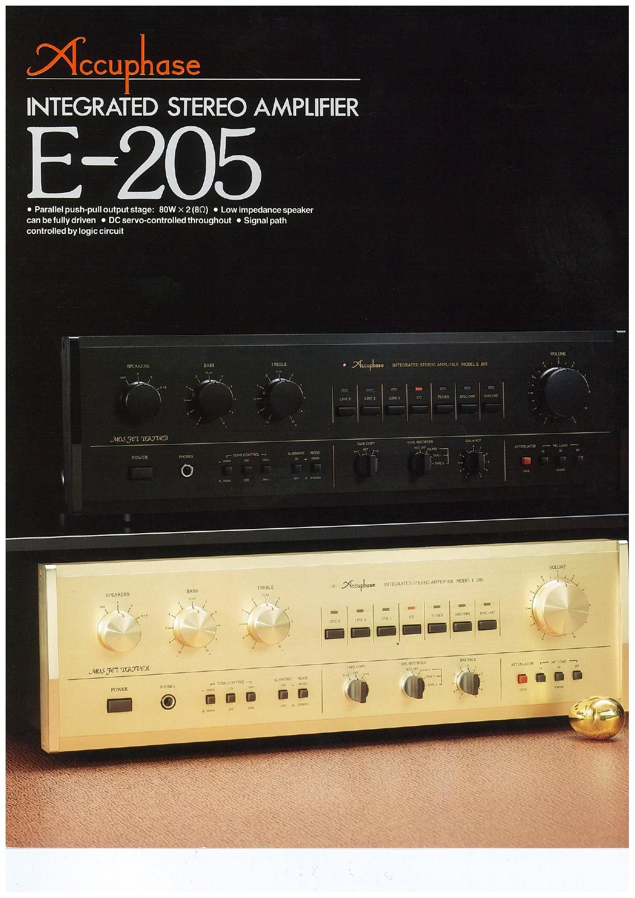
The Accuphase E-205 Integrated Stereo Amplifier has been perfected, drawing on the
sophisticated development technologies accumulated in the field of high-class separate
amplifiers. The E-205 has a rated power output of 80 watts/channel at 8 ohms (20 Hz to
20,000 Hz; distortion ratio less than 0.02 percent) targeted to equal the high-quality power of
such separate amplifiers.
Qualify power, namely, the power necessary to reproduce excellent sound quality is
strongly demanded in this era of digital program sources such as CDs (Compact Discs),
digital tape recorders, BS (Broadcasting Satellite), and so on. However, a large power
output alone is not sufficient to perfectly reproduce the sound from these sources with
excellent presence as well as with musical detail, depth, diffusion, and sonority. That is
where it differs from Qualify power, a synonym for reproduction capability of such real
presence. To achieve Quality power, the E-205 was designed based on carefully selected
circuit elements, ample margin of reserve power output, component layout conducive to
stable operation, rugged construction, etc, adhering to Accuphases development
philosophy to challenge all aspects to the limit.
We paid special attention to the capability to drive low-impedance loads, which is a
fundamental requisite to materialize high-quality power. As a result, the E-205, with its
powerful output stage and large power supply, has a rated power output of 110
watts/channel at 4 ohms. Furthermore, it is able to deliver adequate power even when the
load impedance is 2 ohms, meaning the delivery of adequate energy with the highest
stability and fidelity to any type of speakers.
Nowadays, the sound of the video equipment such as VCR (Video Casette Recorder) is
generally reproduced by an audio system. To cope with these trends, an amplifier must be
able to cope with connection to many program sources. A record player, a tuner, a CD
player, two tape recorders, plus three other program sources can be connected to the E-205
and the desired program source selected by merely a touch.
driven by a MOS FET driver
stage. Large power supply and
powerful output stage drive even low
impedance loads (2 ohms).
1 Parallel-push pull output stage
The circutt diagram for the power amplifier
section is shown in Fig. 1. The power
output stage employs a parallel push-pull
configuration, providing a rated power
output of 80 watts/channel at 8 ohms so
that an adequate power is output. The
advantage of the E-205 lies in the driver
stage that is the preceding stage to the
power output stage. As can be seen from
Fig. i, the driver stage consists of MOS
FETs. A MOS FET is an ideal element for
the driver stage from which a low output
impedance and a high driving voltage are
required. This driver stage. along with the
low emitter resistance in the output stage,
provides extremely high-quality output,
free of notching distortion.
The output stage of a power amplifier
provides the energy to the speakers. The
actual impedance of a speaker fluctuates
a lot across the speakers frequency
range. Consequently, the actual impe-
dance of a speaker system having a
nominal impedance of 4 ohms may drop
to as low as 2 ohms or below for some
frequency ranges. Therefore, a power
amplifier should be capable of supplying
sufficient energy to the low-impedance
loads. On the other hand. an increasingly
large current flows through a solid-state
amplifier in proportion to decreases in the
load impedance, which may result in
destruction of output transistors. Hence,
the output level for low impedance is
severely restricted. Nevertheless, as digit-
al equipment and devices are increasing-
ly used in recent years, the demand for
amplifiers that can supply sufficient power
to low-impedance loads is growing.
The power amplifier of the E-205 has a
high-power output having a Pc (maximum
power dissipation) of about 400 watts and
is provided With a large-capacity transfor-
mer, which is quite a high capaCity to be
employed in an amplifier of E-205's class.
Thus. an output power as high as 110
watts per cahnnel has been realized at a
4-ohm load. Even when the load impe-
dance is 2 ohms, sufficient outpiit can be
obtained.
Directly coupled circuitry with
DC servo preserves signal
purity from disc input to output.
The E-205 employs a Virtually ideal con-
figuration in which unit amplifiers of all
stages are directly coupled. This con-
struction guarantees that the original sig-
nal is amplified and output in a virtually
unaltered state to provide an extremely
high level of fidelity. To eliminate DC drift
completely. a problem that exists in all
directly coupled amplifiers, a powerful DC
servo is used to stabilize each unit am-
plifier.
I Power Amplifier Unit (Single Che
Drive MOS FET
Final power transistors
IC for DC servo
Final power transistors
High-gain equalizer with a hit
signal-to-noise ratio and MC
input impedance selector swi
ensure the best use of analog discs.
The equalizer amplifier for analog C
employs, as shown in Fig. 2. a sing
amplifier system in which the gain of
high-gain equalizer amplifier is chant
over according to that required by an I
(moving magnet) or MC (moving C
cartridge. in this system. the provisior
an amplifying circuit that can stably or
ate irrespective of any quantita
change in NFB (negative feedback) 2
the taking of proper countermeaSL
against residual noise that may oc
when an MC cartridge is used are imr
tant.
To ensure high stability, the input st:
of the equalizer amplifier employs a bi
strap cascode differential amplifier 0
sisting of transistors and FETs. then
significantly improving the high-frequei
characteristics, the key to high stability
the next stage is a high»performai
operational amplifier followed by a or
plementary push-pull circuit in the l
stage. Thus, the amplifying cirCUit hav
such a fundamentally pure and sin"
configuration excels in stability.
Regarding the signal»to-noise ri
when an MC cartridge is used for
input, the residual noise is significa
reduced by employing in the input stz
six FETs connected in parallel. When