Accuphase DP 80 L Brochure
This is the 8 pages manual for Accuphase DP 80 L Brochure.
Read or download the pdf for free.
If you want to contribute, please mail your pdfs to info@audioservicemanuals.com.

Extracted text from Accuphase DP 80 L Brochure (Ocr-read)
Page 2
inwwt (mums; t lyk' ii owi- ixi mt
A major advantage of digital audio
is the possibility to fully recreate
in the home the vibrant quality of
the original musical performance-
whether recorded at the studio or
in the concert hall.
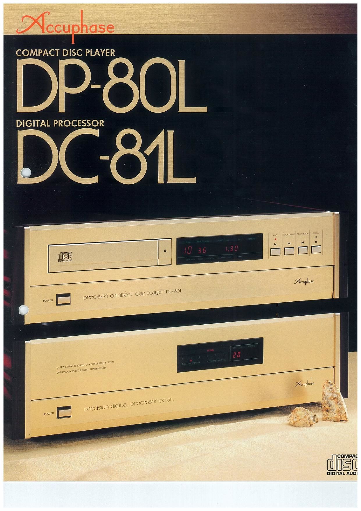
The Accuphase separate type CD
player DP-BOL/DC-81L is the
ultimate instrument to turn this
CD PLAYER DEVELOPMENT
PRINCIPLES
Basic performance comes first
In the world of analog equipment. it is possible to
give a component a certain sonic character
which can enhance its aural impression Digital
components, on the other hand. have to transmit
the entire musical information in encoded form.
If even a small piece of this information is lack-
ing, the result will sound distorted. When de~
veloping digital equipment. it is therefore impor~
tant to first ensure that all the information is
transmitted one hundred percent Only after ex»
ploring the limits of physical performance can
the designer attempt further measures to in-
fluence sound quality. Trying to cover up incom-
plete [)8le performance with cosmetic circuitry
"enhancements" Will not yield results which
satisfy critical ears,
Overall balance is vital
Various techniques to improve CD performance
such as oversampling digital filters. D/A conver-
ters with higher resolution. etc. have been de
veloped, All of these certainly have the potential
to enhance the sound of a CD player. but it does
not suffice to make improvements merely in one
or two limited areas For such measures to be
truly effective. they must be part of an integrated
approach. Especially at the high general level of
performance that has been achieved by modern
audio equipment. further improvements can
only be realized through a harmonious. carefully
balanced reevaluation of the system as a whole.
RF technology - an essential aspect
The signals handled by digital components
have extremely wide bandWidth extending into
the VHF range. is the frequency of television
broadcast signals. Many lesser components
have problems when it comes to correctly
dealing with this aspect. If spurious RF noise
components are allowed to enter the audio cir-
cuits, the result is interference leading to a dis-
tinct degradation of sound quality. The disastrr
ous effect FlF emission can have on sound ref
production is clearly evident when an insufe
ficiently shielded computer is placed close to a
piece of audio equipment
It is therefore of utmost importance to prevent
digital signal interference and spurious noise
emission. In ordertc effectively achieve this aim.
a solid background not only in building audio
equipment but also in RF technology is highly
desirable. This will make it possible to create a
truly state-ofatherart CD player.
ideal into reality. Leaving the area
of merely adequate performance
far behind, this ultimate Compact
Disc reproduction system pushes
back the theoretical limits of
music reproduction. It is a work of
supreme quality in the true
Accuphase spirit.
Based on the above principles, Accuphase has
thoroughly reevaluated every aspect of CD play-
er performance The result is a new pinnacle in
the art of music reproduction.
CD PLAVER DP-BOL
Fig l shows the block diagram of the CD Player
DP-SOL. This unit is desrgned to read the en
coded information from the disc, convert it into
an electrical Signal using an EFM decoder and
to restore the signal to its correct order with the
error correction cichItry The output Signal sup-
plied by the DPA80L is still in digital form, It must
therefore be used together with a separate D/A
converter unit such as the Digital Processor 00
81L Three output terminals are provided two
optical outputs conforming to the EIAJ standard
proposed by Accuphase and one coaxial out-
put. By using the optical output and the supplied
optical fiber cable. transmission losses are re-
duced to an absolute minimum. thus faithfully
preserving even the most delicate musical
nuances
The drive assembly uses a newly developed
mechanism which can accommodate 37inch
CDs, The drive is mounted on an aluminum
diecast frame for absolutely stable operation
The extremely heavy and sturdy construction
shuts out internal as well as external resonances
to maintain optimum sonic purity, The enclosure
provides a Virtually hermetic shield, which to-
gether With the professional-quality AC line filter
eliminates noise interference
The front panel of the player is a model of
functional simplicity, possessing only four
buttons for Play. Pause. and Track Search The
controls for all other functions are located be,
neath a hinged sub panel door in the lower
section The highly pleasing. uncluttered esthea
tic appearance evokes the feel of a high-quality
analog record player. But convenience is not
sacrificed for good looks. A supplied long-range
remote commander permits convenient opera-
tion of the unit from any location.
DIGITAL PROCESSOR DC-BIL
The block diagram of the digital processor unit
DC-81 L is shown in Fig, 2. A total of SlX inputs for
digital signals are provtded: three optical inputs
conforming to the EIAJ standard and three in,
puts for 75-ohm coaxial cable. The unit also is
equipped to handle three sampling frequencies.
48 kHz. 44.1 kHz. and 32 kHz. The DC-Bi L
therefore can accommodate several CD players
and can be used as a decoder also for a digital
satellite broadcast tuner or DAT recorder.
It has become widely realized that the BIA con-
verter has a decisive impact on sound quality. In
the DCaBlL. 20-bit conversion is used. which
represents the current ultimate in D/A resolution
In true Accuphase tradition. the converter is
made up of ultra-preCise discrete circuit compo-
nents for all bits. By carefully optimizing the vital
Circuits of the entire unit. zero-cross distortion is
totally eliminated. This results in D/A conversion
of previously unattainable precision
The digital filter is a 20-bit type with Slim -
oversampling. Its truly amazing performanct)
illustrated by specifications such as the attenua»
tion of -1l0 dB and ripple of :0.00005 dB, The
fact that the filter and converter of the DC781L
are designed to handle a full 20 bits may seem
like overkill." as the Compact Disc format pror
Vides only for 16 bits. However, there are tang-
ible advantages to this approach. The higher the
bit rate of the filter and converter. the lower are
conversion errors and noise in the output. even
With a 16bit input In addition. the digital filter of
the DC-81L also incorporates a noise shaper
which reduces quantization noise to an absolute
minimum.
For even higher performance. the digital filter
and D/A converter block are electrically isolated
from each other, A total of 42 high-speed op-
tOIsolators are used to transmit the Signals be-
tween the two blocks This total isolation be-
tween the digital and analog sections effectively
prevents noise interference and sound quality
degradation. Of course. the power supplies are
also kept completely separate. ustng dedicated
power transformers
The analog filter Is a GIC 3-pole Butterworth type
active filter built with components specialJ
selected on the basis of their sonic perform-
ance The final output stage consists only of a
directrcoupled discrete buffer amplifier with
zero gain. for pure and straight signal transmise
sron
In addition to conventional unbalanced outputs,
the DCVBiL also prowdes a set of balanced XLR
connectors. This ensures that the quality of the
CD music signal is not impaired when sent to the
amplifier. The digital output level control uses
the full 20-bit potential for highly precise opera-
tion in l-dB steps,
The use of highly sophisticated technology cou-
pled with the typical Accuphase attention to
detail has resulted in a CD player system that is
second to none.
Page 3
DP780L, A professionaquuality line lilter is used
to block any interference through the AC power
line,
1 1 Simple and beautiful Accuphase
design
The lronl panel presents an uncluttered appear-
ance, as the controls are located behind a hing-
ed sub panel door. The brushed gold aluminum
linish and the side panels made of exquisite
persimmons wood further enhance the visual
appeal of the unit The D081 L perfectly matchr
es other Accuphase components and blends
harmoniously with the listening room.
The digital processor DCVBIL employs a digital ltlter with B-times oversampling A digital ltller is
a circuit which carries out the liltering process while the signal is still in digital torm Unlike
analog tillers, the operation principles ol digital tillers are quite complex The lottowing is a duel
outline or the concept cl digital liltering
I The D/A converter output contains a large amount at high-trequency noise
components which must be removed by a low-pass irttor
Fig l shows the circuit ccntiguraiion or a conventional CD player lroni the D/A converter to the
output As the input signal to the converter is sampled at 44.1 kHz. the original wavetorm (3)
becomes superimposed with the 44 l kHz square wave signal resulting in the staircase
wavelorm lb) The output or the D/A converter contains the spectrum shown in Fig 2 (a) in
addition to the audio signal extending up to 20 kHz. there are highrlrequency noise components
at multiples oi the sampling lreouency (44 1120 kHz, as 2:20 kHz. l32 3:20 kHz, etc).
teaching into the range ol radios lrequency signals Although these signals are outside the
audible range, their removal is very important. as they can cause the lotloyving proolems
(l) lntermodutation distortion in the nonlinear. ultrahigh lrequency range or audio circuits in the
processor unit. preamplirier. or power ampliiier Such modulation generates distortion
products which spread into the audible range and can degrade sound quality
(2) intrusion or noise components into other equipment such as tuners or tape recorders.
causing the same problems
(3) Output stage overload in Wide-band amptiliers (such as all transrslor amplitiersl oue io
constant lllghrlrequency current.
(4) Overheating and damage or loudspeaker voice coils (especially tweeters) due to excessive
high~lrequency energy
yr the above reasons. every CD player requires a llller to Cut all highrlrequency noise
components above 20 kHz and to correctly restore the original signal.
I Low-peas tillers with sharp cutorl tend to degrade irequency response and phase
characteristics
A low-pass litter. as its name implies. is designed to let signals below a certain irequency pass
and cut oil higher irequencies A desirable characteristic lor CD players is ltat response (no
attenuation) up to 20 kHz. and sharp attenuation above that, reaching at least
(preleraoly -90 dB) at 24 kHz Low-pass tillers are also used in other audio components such
as preamplitiers, out the steepest slopes are usually - l8 dEl/ocl,
Fig 2 (b) shows the characteristics at a *18 dB/Oct tiller. At 46 kHz, attenuation IS *18 dB. at
50 kHz. il is *36 dB. and al 160 kHz, it reaches -54 dB. For a CD player. lhls cl course Will not
do. In Order lu achieve [he required characteristics shown In Fig. 2 (CL several litters can be
employed in tandem (multirpple tillers), out it is a very diilicult teat to ensure llat response to 20
kHz while introducing steep cutolt above this point.
in conventional CD players, lirotder litters were oiten employed, but such designs invariably
introduce phase distortion and cause undulations (ripple) in the lreouency response. Another
disadvantage or such analog lillers is the large number or circuit components required, which is
an additional cause tar nonlinear distortion.
ll it were possible to use ltlters Wilh a more gradual rollrolt these problems could be eliminated
The digital lilter approach provides the ideal solution which does exactly that.
I Digital litter increases sampling troguency to multiples or u i rim. permitting
gentle analog lllter characteristics
Fig 2 (d) shows the lrequency spectrum when the sampling lrequency is multiplied by 5 times.
lo 352.8 kHz As lhe components which have to be removed are now lat Outside the audlble
range. the low-pass lilter can have a gentle cutoli slope. which is highly desirable in view or
phase and ripple characteristics The purpose oi the digital litter is to periorm the arithmetic
rations required to multiply the sampling ireouency The coniiguration or a CD player with
lal llller is Shown In Hg. 3. The D/A converter is preceded by the dtgital lilter and lollowed by
the analog low~pass tiller.
igltal Filters
(c) Wavelorm after passing
(a) Original wavelemi (o) D/A oovener output low-pass tiller
1
portals-cw nevi o-. mm" mm :3 0mm
M
Fig. 1 Contiguretion oi Typlcol co Player
Won swims rmmrlroqaancy hour tango
radio
bind
t l t I I i I l I
a f : i
r i
i i l i l l | i l
I | I I i l I I I
may i t r r l l t t r
zoo «iii semi lanai nuii 2am 2646K Marti 3523K Free
(2 tori-st taiirriosi t4 tum) (srirriosl is tint-st irriml lotirnosi
(I) DIA convert" output contnlm I considerable amount
of high-hlquemy nolu component:
Wed
moo
band I r i l i I I I l
o -_ - .-+-1 F'T: l" f-n r-f-«I {1 '1 r 1-1 r-+l--i r-T'
I i [memlflmlw:: I H i H |
lllllllillll
vllfla i i t I I |
2m uiii ma \IaZJk trim 2209i 2646K soon
tat-nos (a {nest (II-m Ilm\ /15Iym)ls hm) triirririsi fgfmzsfmumy
WW mmsmn/m
90 as (h) Convention-I -1B its/oat. filter cannot ramnv.
a hlghe troquency nolu uttsllotorlly
um
5"" I i I i l- I l I l
a -l-- - - -+- - - - -a ~r- - -1r--+- ~4-
FilTI-llil'ftll'i iFtlTIti ilrl
iiItllttiiltiiilltilttiiil
lItlllltllliltlltlllllttl
we ittttriittittttliittiiiit
20k\«.ili am 1323 no. 220. 26¢in :40qu 3523i Froqmmy
t2 irrnesi [3 tun-st ll uni-st (st-most (SIM!) trims) (aims)
(c) Mum-pole Analog llltor developed for CD players
W
vireo
hum I
a cinch mlmctonsltc .- - +--,
Momgmnllmnfla) : : I
I
I I I
made I I I
2m max Frequency
ruiimcsl
(d) Mlmu nvnumpllng Increases nmpllng lraquency to
352.3 kit: and porrriltc use or gentle rlltar stops as In (D)
Fig. 2 DIA Converter Output Spectrum, Low-pus Flltcr
Cmrmerlnlcs and oversampling
wiet sewing Anselm-l wflh High-Imam
signal at 592 It: hiph- Squaw noiu noise is alimulod
333a MJ km W W W Audio slow-I
at oorrverur ramp. :0 output
Fly. 3 Operational Concept at Digital Ovemmpllng Fitter
Page 4
Peerless optical fiber transmiSSI n
Highly rigid massive construction Diecast mechanism frame
\r
\
The DCrBlLotterstwoopticaloutputoonnectors
which correspond to the ElAJ standard that is
proposed by Accuphase and is known as the
Digital lntertace standard In addition. a cameo
tor for 7570hm coaxial cable Is also provided
The transmisSion rate of the wrderband optical
connection is a full 10 MBit/sec When the sup-
plied high quality optical liber cable is used,
this ensures transmission purity of the highest
order without any degradation of signal quality
As the player and processor units are electrical
ly isolated lrom each other any nOise interfere
ence is eltectively prevented A professional
quality line lilter blocks possmle Interlerence
through the AC power line
The reference Signal tor varlous control lunc-
tions Within a CD player is created by a crystal
clock oscillator In conventional players two
osCillators are used for the digital Signal proces-
sing circuttry and lor the microprocessor. This
approach has a distinct disadvantage, Even a
slight lreouency difference between the two
clock signals can lead to beatsi which in turn
impair sound quality As can be seen from Fig l,
the DP-80L uses a srngle master clock to control
the entire operation of the player. Thls leaves no
room tor sound quality degradation
A great advantage ol the CD tormat is easy track
selection at the Simple touch ot a button. The DP-
80L minimizes track access time with highly
sophisticated technology A linear motor mech»
anism moves the laser pickup under exclusive
control ol a specrally developed 8»bit micropror
cessor, Thanks to this approach locating any
track never takes longer than one second Disc
tray action also is exceptionally smooth and
switt with excellent (eel
4
onion. ourvur i
DVYlCAL
rams
umm
\IN
nIYIcAL ouwur 2
orrchL
1mm,
MlYTER
__© :quIAL ourrur
mm hm
._
N resist
/ MEAD CORREUOR ENCOHDEH
ester 3%
mm Eggwov
mus. Mum. l we.
Rim mm snowman in T roam
._
MEN! comnm. 'S'U"
A DRWEH WWYER WE
WWW it Von/tat 15v
sittcrnn Eggs Remit/tron ->.nmimi
a.
mm 1 can
W,
W
W
Fig I DP-iBoL Brook Dhgnm