This is the 4 pages manual for Accuphase DF 45 Brochure. Read or download the pdf for free.
If you want to contribute, please mail your pdfs to info@audioservicemanuals.com.
Page: 1 / 4
Extracted text from Accuphase DF 45 Brochure (Ocr-read)
Page 1
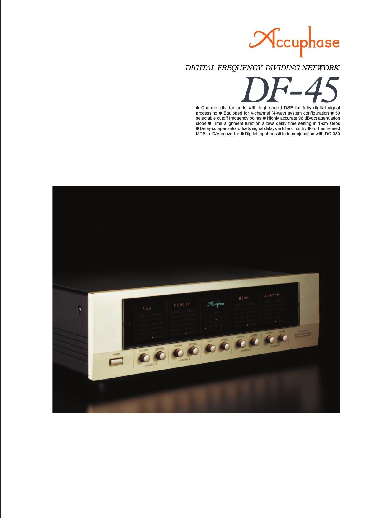
Multi-channel divider with fully digital signal processing -� High-speed 40-bit floating
point DSP provides the processing power for four channel units supplied in standard
configuration. Choice of 59 cutoff frequency points ensures total flexibility. Highly
accurate digital filters enable 96 dB/octave slope characteristics. Time alignment
function adjustable in 1-cm steps, plus delay compensator for offsetting filter circuit
delays ensure superb spatial accuracy. HS-Link capability provides SA-CD support.
Unbalanced
Balanced
Buffer Digital
Inputs
Analog
Inputs
Left
Analog
Outputs
Right
Analog
Outputs
Unbalanced
Balanced
Master LevelDigital Filter
Master LevelDigital Filter
Frequency Level Phase
Subwoofer
Slope Delay Delay Comp Output
DSP
Floating Point DSP : Digital Signal Processor
DAI
Decoder
Encoder
Clock
Distributor
Micro-
computer
Digital
Output
Channel A
Channel D
Display
Coaxial
Transceiver
Coaxial
Receiver
Optical
Receiver
HS-Link
Receiver
A/D
Converter
A/D
Converter
Channel C
Channel B
BalancedHS-Link
UnbalancedCoaxial
Coaxial Optical
Coefficient
Memory Buffer
Sampling
Rate
Converter
Analog
Attenuator
ON/OFF
Analog
Attenuator
ON/OFF
MDS++ D/A Conversion System X4
MDS++
D/A Conversion System X4
Channel dividers based on fully digital signal
processing
The central task of a multi-amp system is of
course the division of the frequency spectrum into
multiple bands or channels. The channel dividers
in the DF-45 feature an impressive array of
sophisticated digital technology based on a DSP
chip with amazing power. The high-speed 40-bit
floating point design of this device makes it
possible to implement all filtering and delay
functions as well as phase and level control in
fully digital form. With minimal temperature drift
and excellent long-term stability, this ensures
filtering performance of the highest order.
High-speed 40-bit floating point DSP assures
precision digital filtering
As a crucial circuit element, the digital filter is
configured with a high-speed 40-bit DSP that has
a 32-bit mantissa and 8-bit exponent section. The
floating point principle enhances calculation
accuracy and results in dramatically improved
dynamic range. This allows the implementation
of extremely steep filter slopes of up to 96 dB/
octave.
59 selectable cutoff frequency points
Filter frequency points can be set over the range
from 31.5 Hz to 22.4 kHz in 1/6-octave intervals.
Same as Channel A (no Subwoofer in DSP )
Fig. 1 DF-45 Block Diagram
Same as Channel A (no Subwoofer in DSP )
Same as Channel A (no Subwoofer in DSP )
In addition, 10, 20, and 290 Hz points are also
provided, resulting in a total of 59 points. Each
divider unit is fully flexible and allows free
selection of the lower and upper cutoff frequency,
for configuration as a low-pass, bandpass, or
high-pass filter.
Six filter slope characteristics up to 96 dB/
octave
The filter attenuation characteristics can be set
to 6 dB/octave, 12 dB/octave, 18 dB/octave, 24
dB/octave, 48 dB/octave, or 96 dB/octave. Within
each unit, separate settings for lower and upper
slope are possible, resulting in a wide variety of
combinations.
Time alignment function allows adjustment in
1-cm steps
When multiple speaker units are used,
differences in sound source location
(diaphragm position on the front/back plane)
will lead to different arrival times of the sound
at the listener's ears. Time alignment is a
function designed to compensate for such Multi-amplification is regarded as the pinnacle of the
audio world. The term refers to dividing the musical
spectrum into several distinct bands and handling each
of these using a dedicated power amplifier and directly
connected speaker unit. When configured and adjusted
properly, such a system can achieve sound
reproduction on a scale that is not possible by any
other means. Sonic definition and spatial imaging can
be optimized by the user to obtain exactly the desired
result. Configuring a multi-amplified system affords truly
one of the greatest pleasures of audio.
The Digital Frequency Dividing Network DF-45 repre-
sents a further evolution
of the model DF-35.
Only the latest digital
technology is employed
throughout, and all inter-
nal signal processing
occurs fully in the digital
domain. High-speed 40-
bit floating point DSP
chips allow super-precise high-order filtering with a
slope of 96 dB/octave. This in turn enables the digital
input to handle sources up to SA-CD quality. In addi-
tion, balanced and unbalanced analog inputs are also
provided, and the unit comes as a 4-channel device
(for 4-way amplification) in its standard configuration.
Each channel in the DF-45 is handled by a dedicated
unit. A full array of functions including frequency dividing
filters (low-pass, band-pass, high-pass), attenuation
slope characteristics, delay and delay compensator
function, level control, and phase switching are
implemented in the digital domain. To store parameter
settings for various scenarios, five memory positions
are provided.
The DF-45 allows the user to select cutoff frequency
settings for adjacent bands from 59 choices, plus six
different attenuation slope settings (max. 96 dB/oct).
This unprecedented flexibility makes it possible to elicit
optimum performance from every speaker unit,
achieving a smooth transition between bands and
ensuring exactly the desired overall energy balance. A
high-quality multi-amp system built with the DF-45 will
sound its very best.
[Hz]
[dBr] PASS
6dB/oct 6dB/oct
1
2
d
B
/o
c
t 12dB/oct
18dB/oct 18dB/oct
24dB/oct 24dB/oct
48dB/oct
48dB/oct
96dB/oct
96dB/oct
PASS
Frequency Fig. 2 Divider unit slope characteristics (bandpass filter)[Cutoff frequency setting 100 Hz for lower and 1 kHz for upper range]
differences. The DF-45
incorporates this in the form of
a DELAY function that
electrically adjusts the time
when the sound from each
driver reaches the listener.
In Figure 3, the sound from the
two speaker units [L and H]
at the start exhibits a time
difference of t seconds due to
the front/back distance d (cm)
of their respective diaphragms.
In order to eliminate this
difference, the delay function
delays the sound of the (H) unit
by t seconds. Normally, a delay
would be expressed as a time
value, but since the delay here
is caused by a spatial distance
(of the two diaphragms), the
DF-45 converts the delay into
a distance value (cm) and
shows this value on the display
for easier understanding.
High-speed 40-bit floating point
Digital Signal Processor (DSP)
Circuit assembly
with high-speed DSP
Page 2
t=34,000d
d cm
L
Delay
Delay
H H
L
DAC 1
DAC 2
DAC 3
DAC 4
(seconds)