Accuphase C 270 Brochure
This is the 6 pages manual for Accuphase C 270 Brochure.
Read or download the pdf for free.
If you want to contribute, please mail your pdfs to info@audioservicemanuals.com.

Extracted text from Accuphase C 270 Brochure (Ocr-read)
Page 1
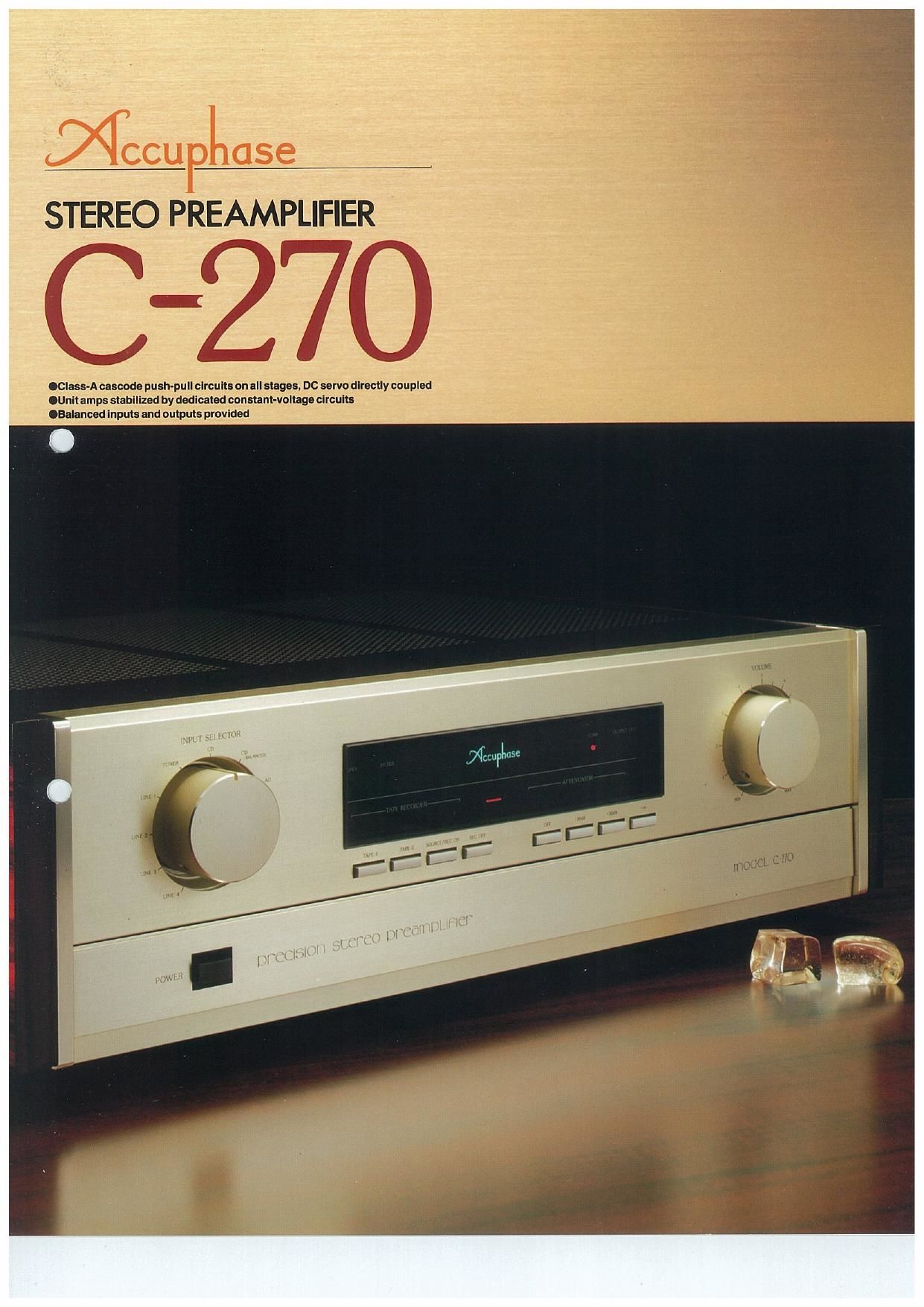
STEREO PREAMPLIFIER
., , 7,7",7/
.CIass~A cascade push-pull circuits on all stages, Dc servo directly coupled
.Unil amps slabllized by dedicated constanl-voltage clrcuils
.Balanced inputs and outpuls provided
Page 2
gs.
. On the mother board, unit amps, filter
capacitor," and rectifier are mounted,
. L-channel highlevel amp unit
. L»channel balanced input and output amp
unit
Recent years have seen amazing, rapid prog-
ress in the technologies of digital tape recorders
and compact disc players so that various high
quality program sources may be enjoyed.
The improved quality of such things as pro-
gram sources. CDs, turntables, and tape record-
ers accordingly calls for parallel improvements
in reproduction devices, especially preamv
piifiers, since they are chiefly responsible for the
quality of the reproduced sounds. In addition.
recent diversification of program sources re-
quires that preamplifiers be able to input various
stgnal sources and offer superb operability.
Accuphases 0-270 stereo preamplifier in-
herits all the tested qualities of the 0-280 that
received a most favorable response from all over
the world. The 0-270 is a preamplifier that opens
a new era, being provided with an equalizer
amplifier whose characteristics have been im-
proved to the Virtual upper limit and a highaievel
flat amplifier with balanced input and output.
While it does not have a built-in head amplifier,
the 0-270 has no fewer than 10 input systems to
cope with a diversny of program sources. Its
amplifier circuit has direct-coupled cascode
push»pull circuits at all stages. which is the ideal
construction. The characteristics of this amplifier
circuit are stabilized by two independent trans-
formers, independent c0iis for each unit am-
plifier, and a dedicated constant-voltage power
supply. This extravagant attention to engineer-
00000000000
L-channel equalizer amp unit
Ft-channel high-level amp unit.
Ft-channel balanced input and output amp
unit
. R-channel equalizer amp unit
ing detail reflects the importance Accuphase
attaches to reproduced sound that faithfull -
veysthe sound quality of the originalsound rm .
One of the 10 pairs of input lines is for bal-
anced input and comes with XLR connectors for
connection to devices with balanced output.
This allows signals to be transferred with no
quality loss and with no adverse effects from
wiring cable noise. in addition to the 10 inputs.
the 0-270 has three outputs of which one is of
balanced type.
Each unit amplifier is housed in a relatively
thick aluminum housing that acts as a noise
shield from external sources and also protects
against malfunctions caused by vibration. The
input and output terminals are finished with high-
grade rhodium plating, offering excellent
mechanical durability and resistivity to corroston
for long contact reliability. The other design
features - the rigid construction employing a
mother PC board of glass epoxy with metal
frame, the distinctive, gold-finished, scratched-
hairline panel made of thick aluminum plate, the
large control knobs, the persimmon
Sideboards, etc. - are the rich extras that
Accuphase adds on top of the best sound tech-
nology. We aim for no less than total owner
satisfaction.
Here's what Accuphase offers in this classic
piece of audio engineering:
Page 3
Class-A Cascode Push-Pull Configuration at Every Stage. DC
Unit Amps Stabilized by Dedicated Constant-Voltage Circuit:
CLASS-A CASCODE PUSH-
PULLCIRCUITSATALL
STAGES IMPROVE HIGH FRE-
QUENCY CHARACTERISTICS,
LINEARITY, AND SIGNAL-TO-
NOISE RATIO
Fig. 1 is the circuit diagram of the equalizer
amplifier and highelevel amplifier. This ideal am-
plifiercircuitconsists ofacascode amplifierahd
Class-A pushepull circuits at every stage, an
Accuphase tradition. This further improves de-
sirable amplifier characteristics to the utmost
limits before negative feedback (NFB) is per-
formed. The cascode amplifier consists of two
elements (transistors) vertically connected so
that the two elements operate as one. This
arrangement increases the input impedance
and gain and simultaneously enhances the
hi requency characteristics. In addition,
lirfity is maintained until the operating limit of
the elements is reached. resulting in decreased
distortion. improved signal-to-noise ratio. and
realization of the ideal characteristics of an am-
plifier circuit, The Class-A push-pull circuitry
further improves the characteristics.
The diagram in Fig. 1 may give you the
impression that the circuit is quite complicated.
However, it basically consists of only three
stages: i) the cascode push-pull differential
amplification stage" (transistors 01 to 011), 2)
the driver stage (transistors Of 2 to 015), and 3)
the output stage (transistors QtSto 021). These
three stages assure high circuit stability.
DC SERVO CONTROL IN ALL
UNIT AMPS PERMITS STRAIGHT
DC OPERATION FROM AD
(ANALOG DISC=LP) INPUT TO
FINAL OUTPUT
The IC in Fig. 1 is the DC servo circuit" that
keeps the output signal to the zero potential by
detecting and feeding back to the input the DC
component generated in the output, In other
x , it prevents DC drift. The IC enables direct
timing of all the signals from the analog disc
(LP) input to the output and thus helps produce
high quality sound that carries no trace of colo-
ration.
10 INPUTS AND 3 OUTPUTS
Lately there has been a growing demand for
audio systems that can be connected even to
video equipment. This demand naturally applies
to preamplifiers, hence it is mandatory that a
preamplifier be provided with multiple input sys-
terns,
Accuphase has responded by providing the
C-270 with 10 inputs. Four are line inputs while
the others are for analog disc input, tuner input,
CD input, and two tape recorders. In addition.
the C270 is the first preamplifier to be provided
with a CD balanced input so that equipment with
balanced output. such as CDs. can be con-
nected. The preamplifier is also provided with
two unbalanced outputs and one balanced out-
put. This is highly convenient for driving more
than one power amplifier at the same time,
Balanced transmission is a transmission sys-
tem widely used in broadcast and studio equip-
ment. The operating prinCIple of this transmis-
sion system is shown in Fig. 2. In this system, the
sender generates positive and negative output
signals, each of which has the same potential as
the other but is out of phase by 180 degrees.
These two output signals are transmitted along a
three-core cable. The ground line in the figure
only connects the zero potential of the signals
and therefore carries no signal current. The re-
ceiver. in turn, receives these sent signals, mix-
ing them with a positive and negative amplifier.
Since the noise picked up by both signals are in
phase when input to the two amplifiers, they act
to cancel each other out. As a result. only pure
signals are input to the amplifiers to be repro-
duced.
TWIN MONO-CONSTRUCTED
INDEPENDENT POWER
TRANSFORMERS; EACH UNIT
AMPLIFIER HAS AN EXCLUSIVE
POWER SUPPLY
Since a signal is generated from a power
source and then returned to it. a power supply
circuit can also be considered part of the am
plifier circuit. Therefore, the quality of the power
supply circuit must match that of the amplifier
circuit. Moreover. the higherthe gain of a pream-
plifier. the higher the quality must be of the
power supply circuit. If the power supply circuit
is inferior, it significantly degrades the quality of
the overall preamp.
The 0270 is equipped with two power trans-
formers which are respectively dedicated to the
left and right channels. Each unit amp has its
exclusive secondary coil. Moreover. to obtain
pure and powerful current, a "multiple power
supply system" is employed by which power is
supplied via a constant-voltage power supply
circuit dedicated to each unit amplifier. Fig, 3
shows the circuit diagram of this system. As can
be seen, the rectifiers and filter capacitors are
placed near the transformers. However. be-
cause constant-voltage power supply circuits
are accommodated in the housing along with
the unit amplifiers. the source impedance can
be kept low. This means the signals are stably
and faithfully amplified,
LOGIC CONTROL RELAYS T0
SHORTEN SIGNAL PATHS
Routing around along signal path for switch
ing the input line or for monitoring tapes can
degrade the high-frequency characteristics. For
this reason, it is best to have the signal path as
straight and short as possible, In the 0270.
therefore, relays are placed at the points of the
signal path where a switch is necessary. These
relays are electronically controlled by logic cir»
cuits.
Obviously, the quality of the relays is a key
factor in such a system. Therefore. the 0-270
employs sealed relays especially developed for
audio applications, They have bifurcated cross-
bar contacts, low contact resistance, and high
durability.
EQUALIZER AMP STRESSING
UNIQUE ATMOSPHERE OF
ANALOG DISC (LP)
The basic circuit configuration ofthe equalizer
amplifier is shown in Fig. 1. Since the level of the
signals to be processed is very weak. they are
easily affected by inherent noise. Therefore, low-
noise field effect transistors (FETs) are carefully
selected for the input,
As well as the circuit configuration. the RIAA
network formed by resistors and capacitors de-
termines the sound quality of an audio system.
The 0-270 employs noninductive capacitors
which were especially developed for audio ap-
piications and thus inductive effect is reduced to
a minimum. These capacitors provide excellent
characteristics outside the audible frequency
range and use epoxy resin as the dielectric to
prevent self-vibration that may be generated by
signal voltage. The 0-270 can therefore repro-
duce the subtle atmosphere peculiar to analog
discs. As the feedback resistors. extremely pre-
cise, gold-foil. resistors are adopted. Their val-
ues hardly change with temperature so that high
stability and quality of the reproduced sounds
are reliably achieved.
RIGID ALUMINUM HOUSING
ACCOMMODATINGAMPLIFIER
CIRCUITS AND CONSTANT-
VOLTAGE POWER SUPPLY
The six amplifiers on the left and right
channels. including the balanced amplifiers.
and the constant-voltage power circuit are
accommodated in a relatively thick. rigid
aluminum housing to shield induction, This
housing serves as well to reduce the effects of
vibration. since the printed circuit board is se-
curely fixed to the housing with screws.
mi
' s 5..
Q _ n O
o. ..
o.
m .-E.
' 1
n. a.
t _ I.
Fig
. 1 Basic Diagram of Unit- Amplifier