Accuphase C 230 Brochure
This is the 4 pages manual for Accuphase C 230 Brochure.
Read or download the pdf for free.
If you want to contribute, please mail your pdfs to info@audioservicemanuals.com.

Extracted text from Accuphase C 230 Brochure (Ocr-read)
Page 1
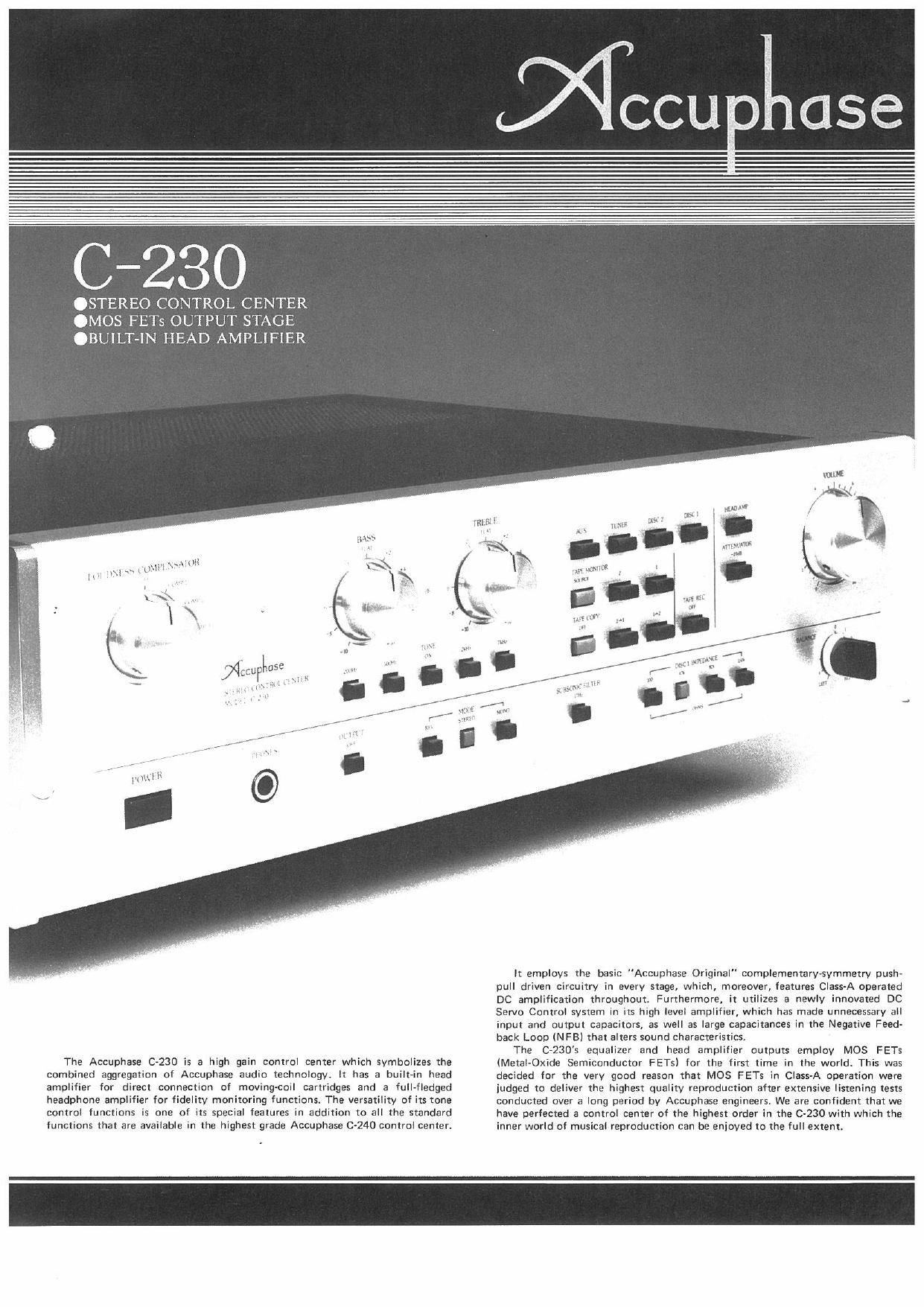
C-230
.STEREO CONTROL CENTER
.MOS FETs OUTPUT STAGE
.BUILT N HEAD AMPLIFIER
, tllnll'lvl'w
,, ~
i l
The Accuphase (3-230 is a high gain Control center which symbolizes the
combined aggregation of Accuphase audio technology. It has a built-in head
amolitier for direct connection of moving-coil Cartridges and a full-fledged
headphone amplifier for fidelity monitoring functions. The Versatility of its [one
control functions is one of its special features in addition to all the standard
functions that are available in the highest grade Accuphase C-240 control center.
lt emuloys the basic "Accuphase Original" complementary-symmetry push-
pull driven circuitry in every stage, which, moreover, features Class-A operated
DC amplification throughout. Furthermore, it utilizes a newly innovated DC
Servo Control system in its high level amplifier, w h has made unnecessary all
input and output capacitors, as well as large capacitances in the Negative Feed-
back Loop (NFB) that alters sound characteristics.
The 0230s equalizer and head amplifier outputs employ MOS FETs
(Metal-Oxide Semiconductor FETs) for the first time in the world. This was
decided for the very good reason that MOS FETs in Class-A operation were
iudged to deliver the highest qualitv reproduction after extensive listening tests
conducted over a long period by Accuphase engineers. We are confident that we
have perfected a control center of the highest order in the 0-230 with which the
inner world of musical reproduction can be enjoyed to the full extent
Page 2
COMPLEMENTARY-SYMMETRY, CLASS-A
PUSH-PULL DRIVEN lCLIInput Capacitor-Less)
DC AMPLIFIER CIRCUITS THROUGHOUT
The keypoint in creating a superior amplifier is to design one with
the best inherent characteristics, together with minimum sound
coloration. The 0230 got off to a good start here because it employs
one of the most extravagant circuits - Complementaryvsymmetry
pushapull drive - in every stage from the head amplifier input to the
final stage output, and also even in its headphone amplifier circuit, The
superior of this circuit's inherent characteristics is outstanding, especial-
ly in linearity, as well as in its very low distortion and very high
stability characteristics. Moreover, the 0230's highly perfected DC
amplifier system has practically eliminated sound coloration by making
unnecessary DC blocking capacitors from the NFB loop as well as all
coupling capacitors in a true Input Capacitor-Less (lCL) design, It also
permits direct connection of phono cartridges which assure higher
quality sound reproduction.
2 MOS FETs USED IN OUTPUT STAGE
One of the advantages of MOS FETs, which are recognized as the
most promising devices for power amplification applications, is that
there is no notching distortion since they are voltage controlled. Overall
characteristics in the C-230 have been greatly improved by employing
MOS FETs in the output stages of its equalizer and high level
amplifiers, It is the first time anywhere that this device has been
utilized in a control center. Accuphase elected MOS FETs for the job
because of their tested effectiveness in further upgrading sound quality.
EXCLUSIVE VOLTAGE REGULATED POWER
SUPPLY FOR ALL UNIT AMPS
Recent active devices are capable of extending the overall band-
width by several megahertz even under ordinary operation. However,
the effectiveness of such wideband amplifiers is halved in the high
frequency range because of circuit impedance, regardless of low
impedance electrodes that might be used. The ideal solution would be
to position a voltage regulated power supply directly at the base of each
amplifying devices.
All the unit amplifiers in the 0230 are equipped with their own
exclusive voltage regulated power supplies. They are located on the
respective unit amplifier printed circuit boards to keep circuit im-
pedance to a minimum. The outstanding stability of the C-230's various
characteristics is due to this almost ideal, extravagant Accuphase design
approach
DC SERVO CONTROL, LOW OUTPUT
IMPEDANCE, HIGH LEVEL AMPLIFIER
It is the normal practice in high level amplifiers to combine a tone
control function and accomplish this by varying the capacitance and
resistance of the negative feedback (NFl loop. In such cases, even a
small DC current in the amplifier output can cause a large pulse type
"shock noise" during switching. A DC blocking capacitor is usually
used to prevent this, but such an amplifier no longer functions as a DC
amplifier and the blocking capacitor will cause sound coloration.
A DC Servo Control System (PAT. PEND) is utilized in the 0230,
as in the case of the C7240, to make such a blocking capacitor
unnecessarvt This innovation permits the 0230 to operate as a pure DC
amplifier even when the tone control is used, since it can hold DC drift
to practically Zero.
Figure 1 shows the high level amplifier with the DC Servo Control
Circuit in the shaded area, enclosed by the broken lines. If DC drift
should appear at the amplifier output, the Servo Control system
operates to control 03, the constant current load of the input buffer
device 0,. In effect, any DC drift detected at the output is amplified
and utilized to control the bias of the buffer 0, and keep the output
always at "0" potential. A big advantage of this Servo system is that it
does not affect sound reproduction since it merely controls the
constant current load of the input buffer device, and does not directy
control the signal path stage.
The capacitive feedback of the buffer device 0, can cause high,
frequency distortion if left unattended. A compensating capacitor m?
be used to prevent this distortion, but it has the disadvantage of alteri
the sound, The 0230 uses a feedback cancelling circuit built around
05, 06, D, and D2 which prevents capacitive feedback and preserves
the sound character at the same time.
SOUND COLORATION ELIMINATED IN
HIGH S/N EQUALIZER AMP
The equalizer amplifier section which faithfully adheres to the
RIAA equalization curve and has a gain of more than 30dB requires the
highest design technology. Figure 2 shows the circuit which is probably
one of the most thoroughly designed equalizer amplifiers ever perfect
ed. Built around 15 active devices,using Class-A operated MOS FETs at
its output to achieve large current drive and low output impedance, it is
designed simultaneously to obtain highest S/N ratio with low im»
pedance of the NF loop. A high S/N ratio that is close to the theoretical
limit was actually achieved by the addition of a high Gm input buffers
The equalizer amplifier also utilizes a feedback canceller circuit built
around 0,, 0,, D| and D7 to prevent sound quality deterioration from
the capacitive feedback of the input device. The design of this input
circuit, to which cartridges with reactance characteristics must be
directly connected, is all important. Capacitive compensation for this
purpose should not be employed because of mutual CR effects that
may alter frequency response characteristics.
Fig. 3 shows the IM distortion data measured with two clot/g)
proximity frequencies under New lHF Measuring Method which we
revised in 1978 and is called as "NEW lHF-IM. This new method
brings out the similar distortion to the dynamic one which could not be
measured by the measuring method of distortion stated afterward and
smvo (IONfRDI.
mum
cn Nitwnfix ron
rm: coNrnoL
mew
ourpur
niAA EOUALlZATlDN ._.
NETWORK
, l Gig
Fig.1 DIAGRAM 0F SERVO CONTROLLED HIGHeLEVEL AMPLIFIER
Fig.2 DIAGRAM 0F EQUALIZER AMPLIFIER