Accuphase C 220 Brochure
This is the 4 pages manual for Accuphase C 220 Brochure.
Read or download the pdf for free.
If you want to contribute, please mail your pdfs to info@audioservicemanuals.com.

Extracted text from Accuphase C 220 Brochure (Ocr-read)
Page 2
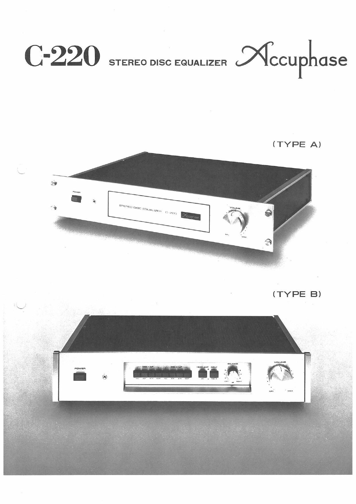
- MCCUFLase C'22O
The unlimited possibilities of phonograph record reproduction become
incredibly,apparent with each new improvement in the quality of sound
reproducing systems. This is noticeable especially with recent cartridge
and speaker system improvements, when backed by top grade amplifiers.
Details of music heretofore completely absent can now be recreated
superbly with such a system that gives new stereophonic breadth and
depth to disc reproduction, while retaining left-right image positions
faithfully.
With such possibilities opening up in disc reproduction, it is natural for
high fidelity enthusiasts to seek ALL the musical information that is
stored in their disc grooves, and enjoy the superb sound that contains the
finer nuances of music.
The Accuphase C-220 DISC EOUALIZER was created to meet the
requirements of iust such true high fidelity enthusiasts. It is the result of
endless listening tests to ensure clear sound of outstanding quality, and
incorporates today's highest level audio technology. It, therefore, ensures
top grade phono equalization performance, and provides correct der
emphasis for a faithful, flat frequency response.
This unit does not contain any AUX or TAPE inputs since design priority
was focused, without any compromise, on a special disc equalizer pre-
amplifier of the highest quality. It was intended from the outset to be
used together with a preamplifier that is already a part of your high
fidelity system.
I] . General Outline
(a) How to reproduce sources other than discs.
Although this unit has no special AUX or TAPE inputs, it is provided
with a separate input to accommodate these other sources which connect
directly to the power amplifier when the POWER switch of the C-220 is
turned OFF.
Figure 'I, shows how this is done. The outpm of the preamplifier in your
possession to which a Tuner or Tape Recorder, or both, are connected. is
routed to the EXT PREAMP INPUT of this unit.
These sources then connected directly to the power amplifier auto-
matically, for radio reception or tape playback, when the POWER switch
of this unit is turned OFF.
Preamplirier 0
Tape
recorder
Record
player
(Fig. 1)
EXT PREAMP INPUT Speaker
Power Amp.
0220 DISC EQUALIZER
Ganged with the POWER sw.
Figure 2. shows how the outputs of a Tuner and Tape recorder that are
equipped with their respective level controls can be routed for direct
connection to the power amplifier through the EXT PREAMP INPUT
jack of this unit when its POWER switch is turned OFF
In this case. the desired source must first be selected with the selector
switch arrangement, as shown.
* Selector Switch
Tuner
40 Output
Tape
recorder
Speaker
Power AmD 4%
Figure 3. shows how the FIXED OUTPUT from this unit can be con-
nected to the AUX input of the preamplifier or control center that you
have for tone control and acoustic compensation.
In this case, the equalizer amp section of your preamplifier is employed
instead, but it is, of course, possible to use the head amplifier section of
the C-220.
Record
player
(Fig- 2)
c-220 DISC EQUALIZER
S eaker
m, # p
Famine. &, power Am... fl
Tape 7
recorder
Tu Aux input
FIXED OUTPUT
c220 DI sc EQUALIZER
(bl Built-in Head Amplifier helps boost total gain to 86dB.
This Stereo Disc Equalizer which is consisted of a head amplifier with a
26dB gain for connecting Moving Coil (MCI cartridges, and an equalizer
amplifier with a 60dB gain has a total gain of 86dB, the highest figure of
any similar component. Therefore, it is fully capable of providing any
gain required for any type of cartridge with any power amplifier com-
bination.
lc) Single Tone Arm sufficient for both MC and MM cartridges.
Because of the large noise created during switching, it is not practica
with most preamplifiers that have a built-in head amp, to use both M
and MM (Moving Magnet) type cartridges with a single tone arm.
It is the usual practice with such preamps to use separate tone arms
which is most inconvenient.
The 0220 employs a relay control to switch the head amplifier in or out
of the amplification lineup noiselessly, as required. It utilizes an elec-
tronic circuit which induces a time lag and activates a muting relay that
cuts off the output and eliminates the switching noise. This makes it
possible to use both MC and MM type cartridges with a single tone arm,
which is a great convenience advantage. An exceptionally excellent and
durable relay with very low contact resistance was carefully selected for
this important function.
2. Circuit Features
(a) Symmetrical Push-Pull Class-A amplification in all driver stages.
An improved version of the symmetrical push-pull circuit which Ac-
cuphase first developed and introduced to the audio world in its Models
P-300 and (3-200 is used in every driver stage.
The special feature of this circuit is its superior inherent low distortion
characteristics even before negative feedback (NFB) application, so that
its final low distortion performance is outstanding. Distortion ratio of
each amplifier stage is less than 0.001% at 1kHz which is close to the
measurable limit.
Moreover, this circuit ensures very stable operation against line voltage
fluctuations. o
(bl Every DC amplifier stage use Class-A amplification.
No capacitors are used in the NF loop of the DC, Class-A amplifiers that
are used in every stage, as well as in the head amplifier. Highest grade
sound of outstanding quality is also due to the most careful selection of
parts, and rejection of those with adverse sound imparting qualities.
(1:) New RET transistors used in head amplifier.
Newly developed Ring Emitter Transistors (RETsl for superior high
frequency power amplification are employed at the signal input of the
head amplifier to comprise a push-pull, differential DC amplifier that is
operated as a Class-A amplifier with a complementary-symmetry output.
This new HET is consisted of 100 low input signal transistors working in
parallel with the ballast resistors at the emitters constructed by its
diffused layer. It thus retains the superior high frequency characteristics
of low amplification factor transistors, while providing the advantage of
very high power amplification.
This unit has achieved a remarkably low noise rating by employing these
new RETs at the input of the head amplifier where signal level is
extremely low. Due to their excellent high frequency characteristic and
parallel structure efficiency, the equivalent input noise resistance is
considerably lower than that of conventional transistors or FETs. These
ReTs are also the major factor for the very low circuit impedance, as well
as the low NFB input side impedance of the differential amplifier since
they can deliver large signal currents to amplifying elements.
The S/N ratio of the head amplifier at its rated input of 0.1mV is 74dB
which approaches the theoretical limit.
Another significant feature of this head amplifier is the very stable center
voltage of its input circuit. This has eliminated the need for an input
capacitor which can greatly harm sound quality.