Page 1
547W
365W
214W
118W
61W
5
0 10 15 20 25
0 5 10 15 20 25 30 35
+ B3
- B3
-
+ +-
+ B1
- B1
- B2
+ B2 Q1
Q3
Q2
Q4 Q8
Q6
Q7
Q5 Q9
Q17 Q21
Q19
Q18 Q20
Q22
Q23
Q24
Q25 Q27 Q29 Q31
Q26 Q28 Q30 Q32
Q33
Q34
Q35
Q36
Q37
Q38
Q39
Q40
Q41
Q42
Q13
Q11 Q15
Q10 Q14
Q12 Q16
-+
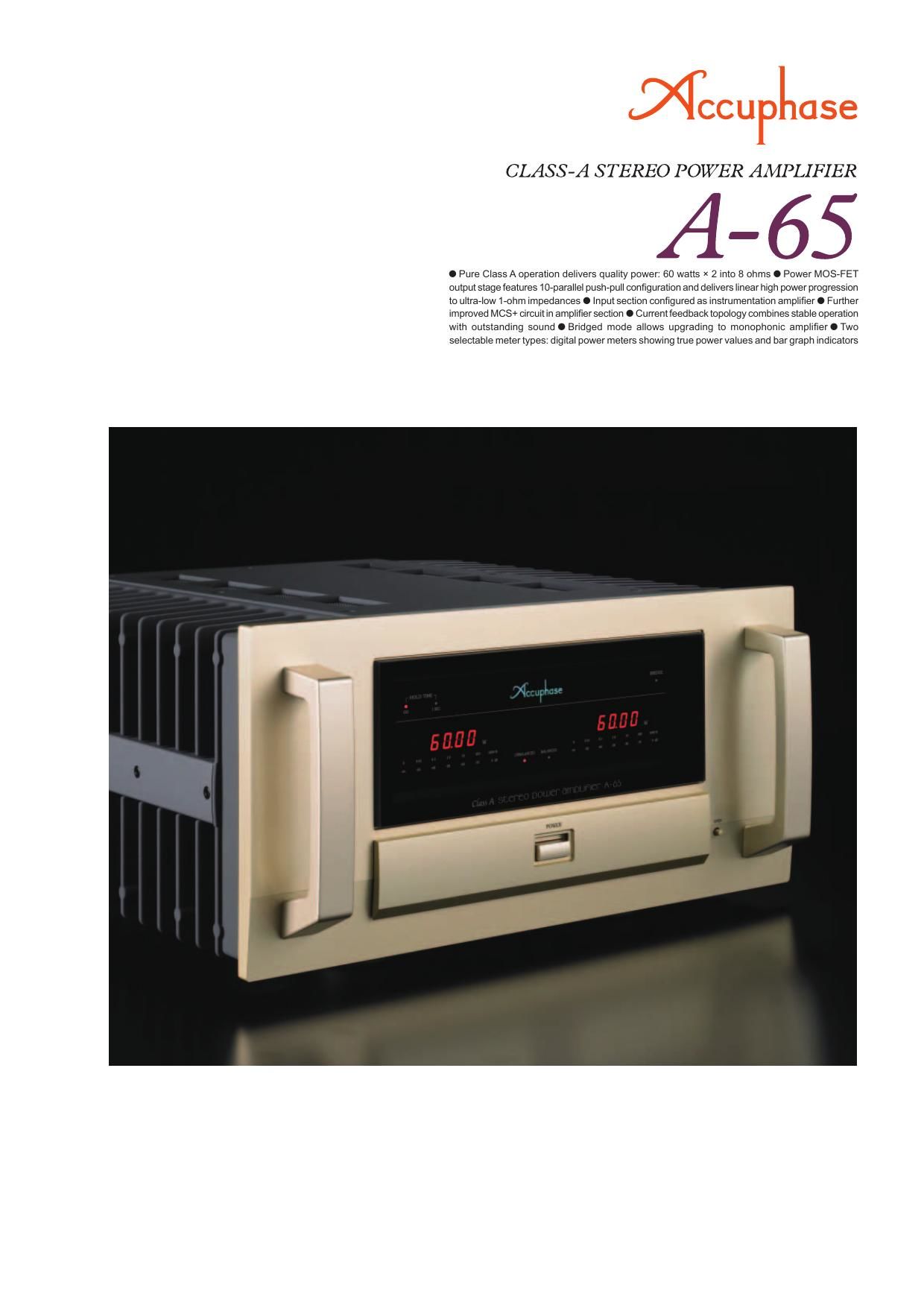
Power MOS-FETs
n Power modules with 10-parallel push-pull arrangement of power MOS-FETs
deliver 480 watts per channel into 1 ohm (music signals), 240 watts into 2
ohms, 120 watts into 4 ohms, or 60 watts into 8 ohms.
n Strong power supply with high-effi ciency toroidal transformer and two
extra-large 82,000 μF fi ltering capacitors.
n
Bridged mode supports upgrading to monophonic amplifi er with 960 watts
into 2 ohms (music signals), 480 watts into 4 ohms, or 240 watts into 8
ohms.
n Instrumentation amplifi er principle allows fully balanced signal paths, and
current feedback amplifi er topology drastically improves S/N ratio.
n Four gain control settings (MAX, -�3 dB, -�6 dB, -�12 dB) minimize residual
noise.
n Fully balanced input stage shuts out external noise interference.
n Dual mode power meters, switchable to 5-digit numeric readout or 25-point
LED bar graph indication.
-�� Meter circuit ON/OFF switch.
-�� Digital power meters show true
output power values, based on
output current detected by a
Hall element.
-�� Peak value hold time settings: 1 second, .
n Input selector button (balanced/unbalanced) on front
panel.
n Mode selector with dual mono position supports bi-
amping.
n Oversize speaker terminals accept also Y lugs.
The combination of pure class A and power MOS-FET
devices to realize high output power with excellent sonic
purity is a domain where Accuphase excels. Models such
as the A-100, A-50V, and A-60 have achieved legendary
status among audiophiles and represent an unrivaled level
of technological excellence. As a model-change successor
to the A-60, the new A-65 incorporates accumulated Ac-
cuphase know-how while featuring a number of further im-
provements. The input stage is confi gured as an instrumen-
tation amplifi er to allow fully balanced input signal paths.
The further refi ned MCS+ topology pushes noise and dis-
tortion down to absolutely minimal levels, and strictly se-
lected materials and parts of the highest quality are used
throughout. The end result is a high-end class A stereo am-
plifi er with simply stunning performance and sound quality.
The output stage of the A-65 features power MOS-FETs
renowned for their excellent sound and superior reliability.
For each channel, ten of these devices are arranged in a
parallel push-pull arrangement. MOS-FETs have excellent
frequency characteristics, and their high input impedance
reduces the load imposed on the preceding drive stage.
They also have negative thermal characteristics, which
ensures perfect operation stability. Driving these devices
in pure class A produces rich, high-defi nition sound that
brings out the fi nest nuances in the music. In a pure class A
amplifi er, the power provided by the power supply is always
constant, regardless of the presence of a musical signal.
This means that the amplifi er remains unaffected by fl uc-
tuations in voltage and other external infl uences.
On the other hand, it also means that the output stage
generates considerable thermal energy. In the A-65, this
is dissipated effectively by large heat sinks which
provide ample capacity to remove the heat pro-
duced by the internal circuitry. The high-effi ciency
toroidal power transformer housed in an alumi-
num diecast enclosure, in conjunction with amply
dimensioned smoothing capacitors, provides the
muscle to deliver an astonishing 480 watts per
channel into a 1-ohm load (music signals only). If
even higher power reserves are required, bridged
mode turns the A-65 into a superlative mono-
phonic power amplifi er.
Pure Class A power amplifi er with power MOS-FET devices - Input stage features ful-
ly balanced signal paths as found in high-quality instrumentation amplifi ers. Further
refi ned MCS+ topology and current feedback result in superb sound quality and out-
standing performance parameters. Strong power supply section and power MOS-FET
devices in ten-parallel push-pull confi guration sustain linear power output progression
down to impedances as low as 1 ohm. Digital power meters show true power readings.
INPUT
Large speaker terminals
Figure 1 Circuit diagram of amplifi er section (one channel)
Hall element Toroidal power transformer
Bias stabilizer
circuit
NFB
NETWORK
Mode selector Gain selector
Meter circuitry/control circuitry assemblyFiltering capacitors
Unbalanced and balanced input connectors
NFB
NETWORK GAIN
CONTROLBias stabilizer
circuit
Bias stabilizer
circuit
Bias stabilizer
circuitNFB
NETWORK
REGULATOR REGULATOR
INPUT
MCS+ (MultipleCircuit Summing) Gain control
Instrumentation amplifi er
10-parallel push-pull
power MOS-FET array
Output voltage (V)
Output current (A)
Figure 2 Load impedance vs. outpu t (output voltage/output cur r
�> 1-ohm operation p with music signal s
OUTPUT Bias stabilizer
circuit
Page 2
40 45
+-
-
+ +-
+-
-
+
n
Power amplifi er assembly
Power amplifier assembly with
10-parallel push-pull power MOS-
FET pairs per channel mounted
directly to large heat sink, MCS+
circuitry, and current feedback
amplifi er.
Instrumentation amplifi er and further refi ned MCS+ topology
Instrumentation amp confi guration allows
fully balanced signal paths
The newly adopted instrumentation amplifi er
principle ensures that all signal paths from the
inputs to the power amp stage are fully balanced.
This results in excellent CMRR (Common Mode
Rejection Ratio) and minimal distortion. Another
signifi cant advantage is the fact that external noise
and other external infl uences are virtually shut out.
The result is a drastic improvement in operation
stability and reliability.
Further refined MCS+ topology for even
lower noise
Accuphases original MCS (Multiple Circuit
Summing) principle uses a number of identical
circuits connected in parallel to achieve superior
performance characteristics. MCS+ is a further
refi ned version of this approach. By extending
parallel operation to the class-A drive stage of the current/voltage converter, the noise fl oor has
been lowered further.
t power ent)
ossible s only
Current feedback principle assures excellent
phase characteristics in high range
As shown in the illustration, the A-65 uses the
output signal current rather than voltage for
feedback. Since the impedance at the current
feedback point is very low, there is almost no
phase shift. A minimal amount of NFB therefore
results in maximum improvement of circuit
parameters.
INPUT
NFB
NETWORK
GAIN CONTROL
CIRCUIT
INPUT
NFB
NETWORK
Signal input stage Power amplifi er stage
OUTPUT
Instrumentation amplifi er confi guration
INPUT
OUTPUT
INPUT
Current NFB
network I/V
converter
Current
adder
Trans-impedance amplifi er Amp-
lifi er
Principle of current feedback amplifi er
Buffer
Buffer