Page 1
n Triple push-pull arrangement of power MOS-FETs delivers 150 watts per
channel into 1 ohm (music signals), 120 watts into 2 ohms, 60 watts into
4 ohms, or 30 watts into 8 ohms.
n Strong power supply with large transformer and high fi ltering capacity.
The power supply features a large high-effi ciency transformer and two 47,000 μF
aluminum electrolytic capacitors selected for sound quality.
n Instrumentation amplifi er principle allows fully balanced signal paths, and
current feedback amplifi er topology drastically improves S/N ratio.
n Bridged mode supports upgrading to monophonic amplifi er with 300
watts into 2 ohms (music signals), 240 watts into 4 ohms, or 120 watts
into 8 ohms.
Simply by setting the mode selector to the bridged position, the A-35 is turned into a
monophonic amplifi er with 4 times the output power as compared to stereo operation.
This can be used when more power reserves are needed.
n Redesigned NFB circuit path results in minimized output
impedance, thereby further improving the damping factor.
This manifests itself in even better sound quality.
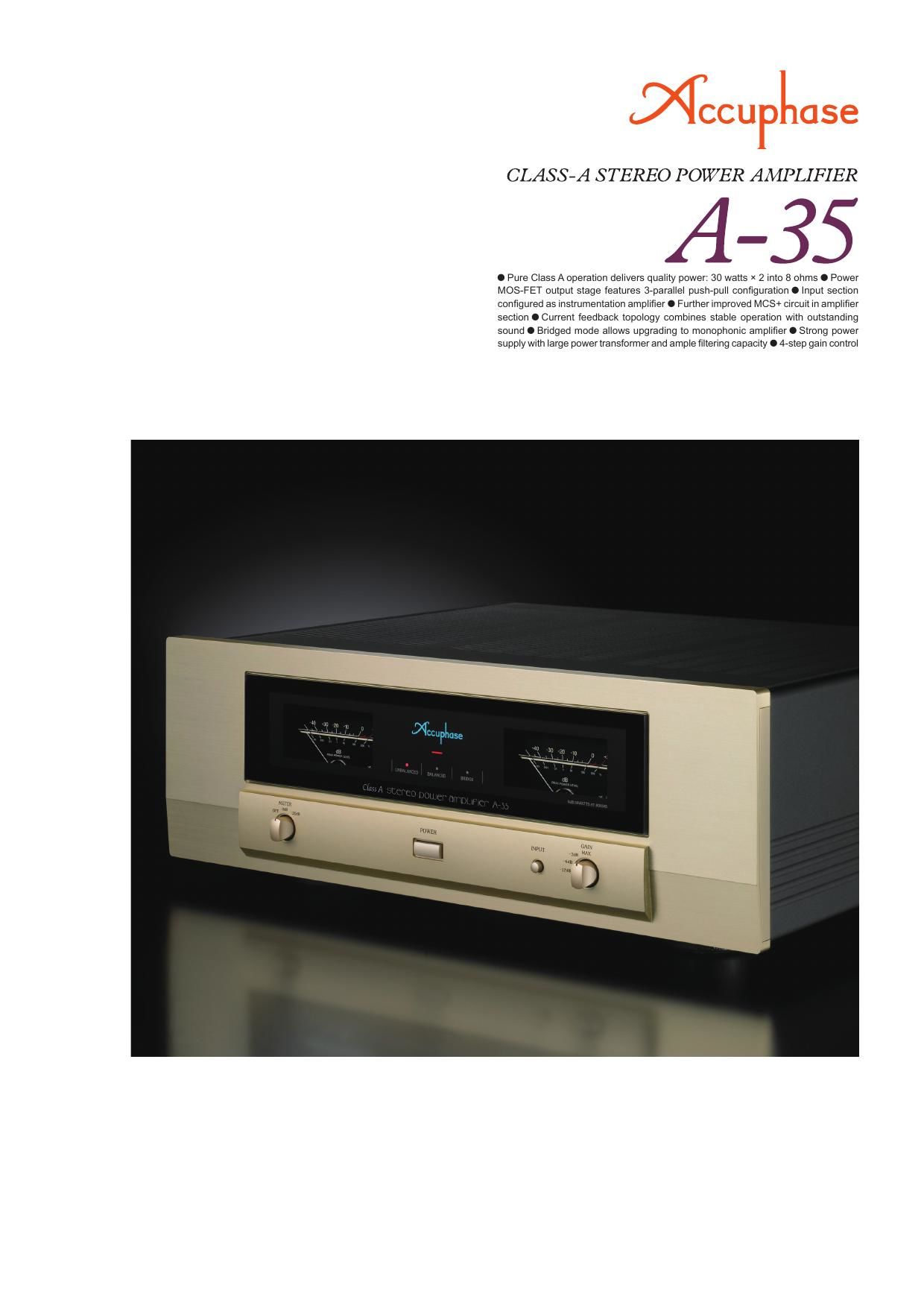
n Analog power meters with off/sensitivity selector.
Meter illumination and operation as well as meter sensitivity (0 dB,
-�20 dB) can be controlled with a selector.
n 4-step gain control also minimizes residual noise.The gain control switches gain in the fi rst instrumentation amplifi er
stage. Four settings are available: MAX, -�3 dB, -�6 dB, -�12 dB.
n Fully balanced input stage shuts out external noise
interference.
n
Mode selector with dual mono position supports bi-amping.
n Oversize speaker terminals accept also Y lugs.
A pure class A amplifi er maintains a constant current fl ow
regardless of the presence or absence of a musical sig-
nal. This makes it possible to create a perfectly stable
sound stage with unparalleled ambience that is the dream
of any audiophile. Within this rarefi ed breed of amplifi ers,
the high-end pure class A stereo amplifi er A-65 has gar-
nered praise the world over as the ultimate reference for
superb performance and sheer sonic excellence. The A-35
was developed as a successor to the A-30 while inherit-
ing many design aspects of the A-65. Dedication to the
best sound possible is always an Accuphase hallmark.
The use of the instrumentation amplifi er principle allows
fully balanced input signal paths, and further refi ned MCS+
topology pushes noise and distortion down to absolutely
minimal levels. In terms of its design as well as its sound,
the A-35 offers a highly attractive entry point to the world
of pure class A.
In the output stage of the A-35, proven power MOS-FET
devices are used in a triple-parallel confi guration for each
channel. MOS-FETs have excellent frequency character-
istics, and their high input impedance reduces the load
imposed on the preceding drive stage. The devices are
directly mounted on large heat sinks for effi cient dissipa-
tion of thermal energy, assuring perfect operation stabil-
ity. Driving these devices in pure class A produces rich,
high-defi nition sound that brings out the fi nest nuances in
the music.
The power supply of an amplifi er is its ultimate source of
energy. Unless it provides ample reserves, sound quality
will suffer, and even basic performance parameters may
not be met. The A-35 has a massive power transformer
and two 47,000 μF smoothing capacitors specially select-
ed for their sonic properties. This sustains an output power
rating of 120 watts into 2 ohms, 60 watts into 4 ohms, or
30 watts into 8 ohms per channel, and it enables the A-35
to perfectly handle even very-low impedance speakers or
speakers with wildly fl uctuating impedance characteristics.
To prevent clipping on occasional momentary high-level
pulses, the maximum clipping level of the A-35 is set to 50
watts per channel into 8 ohms (sine wave output). Use in
bridged mode is also possible, turning the A-35 into a high-
power monophonic amplifi er.
Pure Class A sound thats every audiophiles dream - Input stage features ful-
ly balanced signal paths as found in high-quality instrumentation ampli� ers.
Further re� ned MCS+ topology and current feedback result in superb sound
quality and outstanding S/N ratio and other performance parameters. Strong
power supply section and power MOS-FET devices in triple-parallel push-
pull con� guration sustain linear power output progression down to ultra-low
impedances, with the capability to deliver 150 watts into 1 ohm (music signal).
INPUT
Figure 1 Circuit diagram of amplifi er section (one channel)
Gain selector Power transformer
Bias
stabilizer
NFB
NETWORK
Protection and power meter circuit assemblyFiltering capacitors
Unbalanced and balanced input connectors
NFB
NETWORK
GAIN CONTROL
CIRCUIT
Bias
stabilizer
Bias
stabilizer
Bias
stabilizerNFB
NETWORK
REGULATORREGULATOR
INPUT
MCS+ (MultipleCircuit Summing) Gain control3-parallel push-pull
power MOS-FETs
Output voltage (V)
Output current (A)
Figure 2 Load impedance vs. output power
(output voltage/output current)
�> 1-ohm operation possible
with music signals only
OUTPUT
Bias
stabilizer
Meter selector
Large speaker terminals High-reliability parts selected for sound quality
Instrumentation amplifi er NFB
NETWORK
SPEAKER
TERMINALS
Page 2
n Power amplifi er assemblyPower amplifi er assembly with
three parallel push-pull power MOS-FET
pairs per channel mounted directly to large heat
sink, MCS+ circuitry, and current feedback amplifi er.
Current feedback principle assures excellent
phase characteristics in high range
As shown in the illustration, the A-35 uses the
output signal current rather than voltage for
feedback. Since the impedance at the current
feedback point is very low, there is almost no phase
shift. A minimal amount of NFB therefore results in
maximum improvement of circuit parameters.
INPUT
OUTPUT
INPUT
Current NFB
network I/V
converter
Current
adder
Trans-impedance amplifi er Amp-
lifi er
Principle of current feedback amplifi er
Buffer
Buffer
Instrumentation amp confi guration allows
fully balanced signal paths
The newly adopted instrumentation amplifi er
principle ensures that all signal paths from the
inputs to the power amp stage are fully balanced.
This results in excellent CMRR (common mode
rejection ratio) and minimal distortion. Another
signifi cant advantage is the fact that external noise
and other external infl uences are virtually shut
out. The result is a power amplifi er with drastically
improved operation stability and reliability.
Further refined MCS+ topology reduces
noise even further
Accuphases original MCS (Multiple Circuit
Summing) principle uses a number of identical
circuits connected in parallel to achieve superior
performance characteristics. MCS+ is a further
refi ned version of this approach. By extending
parallel operation to the class A drive stage of
the current/voltage converter, the noise fl oor has
been further lowered.
INPUT
NFB
NETWORK
GAIN CONTROL
CIRCUIT
INPUT
NFB
NETWORK
Signal input stage Power amplifi er stage
OUTPUT
Instrumentation amplifi er confi guration
Instrumentation amplifi er and
further refi ned MCS+ topology