Technics SUA 60 Service Manual

This is the 12 pages manual for Technics SUA 60 Service Manual.
Read or download the pdf for free. If you want to contribute, please upload pdfs to audioservicemanuals.wetransfer.com.

Page: 1 / 12
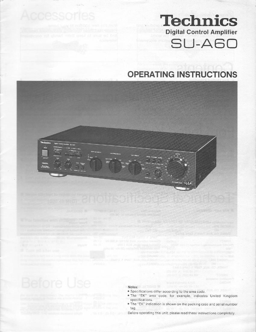
Technics SUA 60 Service Manual

Extracted text from Technics SUA 60 Service Manual (Ocr-read)


Page 1

Technics

Digital Control Amplifier

SU-AB

OPERATING INSTRUCTIONS

Notes:

I Specifications differ according to the area code

0 The EK area code, for example. indicates United Kingdom
specifications.

0 The EK Indication is shown on the packing case and serial number
lag.

Before operating this unit, please read these instruclions completely.

Page 2

We want to thank you for selecting this product and
to welcome you to the growing family of satisfied
Technics product owners around the world.

We feel certain you will get maximum enjoyment

from this new addition to your home.

Please read these operating instructions carefully,
and be sure to keep them handy for convenient
reference.

Contents

0 For United Kingdom ...... 2
0 Technical Specifications ......... 2
0 Accessories ............... 3
0 Suggestions for Safety 3
. Before Use ................ 3
U Connections ..................................... 4

0 Front Panel Controls and Functions .......... 6
0 Operation ........................................ 8
I Recording ........................................ 10
0 Troubleshooting Guide .............. Back cover
0 Maintenance .......................... Backcover

For United Kingdom

The EK Indication is shown on the name plate.
Important

THE WIRES IN THIS MAINS LEAD ARE COLOURED IN
ACCORDANCE WITH THE FOLLOWING CODE.

BLUE. NEUTRAL

BROWN LIVE

As the colours ol the wires in the mains lead of this unit may not
correspond with the coloured markings Identifying the
terminals in your plug, proceed as Iollows. The wire which is
coloured BLUE must be connected to the terminal which is
marked with the letter N or coloured BLACK.

The wire which is coloured BROWN must be connected to the
terminal which is marked with the letter L or coloured RED.

Technical Specifications (mm,

I PRE AMP. SECTION Subsonlc filter 19 Hz, 6 dB/oct I GENERAL
Loudness control (volume at *3!) dB)
50 HZ. +9 dB Power consumption 20W
Input sensitivity and impedance Mutlng 720 dB Puwer supply
PHONO MM 2 5 mV/47kn Output voltage and Impedance For continental Europe AC 50 Hz/GO HZ. 220v
MC 170 LIV/2200 OUTPUT rated 1W) For United Kingdom, Australia and others
TUNER. CD. AUX. TAPE 1. TAPE Z/DAT max. 10V AC 50 Hz/60 HZ, 110V/127V/220V/240V
150 mV/tEkD TAPE, L 2/DAT REC OUT 150 mV Dimensions (WXHXD) 430 X 103 >< 290 mm
DIRECT 1 V/47k0 Channel balance. AUX 250 Hz~6.300 Hz +1 dB (16-15/I6" X 4-1/16 X 11-6/16")
PHONO maximum input voltage (1 kHz, RMS) Channel separatlon, AUX 1 RH! 55 dB Welght 4,9 kg (1018 lb.)
MM 170 mv Total harmonic distortion (20 Ht~20 kHz)
we 13 mV PHONO MM ROW
S/N FHONO MC 0.003%
PHONO MM 79 dB (88 dB. IHF. A) TUNER. CD. AUX. TAPE 1. 2/DAT 0.002%
MC 70 dB (72 dB. 250 V. IHF. A) DIRECT 0,0009%
TUNER. CD. AUX. TAPE 1, TAPE ZIDAT
100 dB (IHF. A, 106 dB)
DIRECT 106dBt|HF.A.115dB)
Frequency response
PHONO RIAA standard curve
0 2 dB (20 H240 kHIl I DIGITAL SECTION
TUNER. CD. AUX. TAPE 1. TAPE 2/DAT
0 5 HZ" 50 kHz (*3 dEl Harmonic distortion 0.001534: Notes:
- 0, -01 dB (20 Hz" 20 kHz} Total harmonic distortion 0,0025% 1. Specifications are subiect to change without
DIRECT 0 B HZ~150 kHz (*3 dB) s/N III 08 notice.
Tone COHIYOIS Dynamic range 99 dB Weight and dimensions are approxrmate.
BASS 50 H1. 10 GB" 10 GE Frequency response 2. Total harmonic distortion IS measured by the
TREBLE 20 kHz, .10 dB» 10 dB 2 Hz--20 kHz. I 0.3 (13,-0.3 dB digital Spectrum analyzer (HP. 3045 System).

Page 9

Listening as is, without passing through the
tone control circuit. etc.

Set the volume to the x" position, and then
switch ON the power".

Set the direct out selector to the "digital".

It'll.

When listening to components connected to the DIGITAL
-] INPUT" terminals:

Select the sound source by using the digital

input.

optical 1: Make this setting when the component to be used

15 connected to the "OPTICAL 1" terminal.

optical 2: Make thls setting when the component to be used

IS connected to the "OPTICAL 2" terminal.

coaxial : Make this setttng when the component to be used

15 connected to the "COAXIAL" terminal.

Note:

When listening to these sources. set the DAT monitor/ext

to Zl'le digital source/out".

3 When listening to digital audio tape (DAT). etc. connected to
i-athe DAT/EXT" terminals:

Set the DAT monitor/ext" to the DAT/in".

Adjust the volume" to the desired level.

:24? to the B scale on oage 8.)
..:s Instance. the tone quallty. etc. cannot be adjusted.

to

Set the volume" to the w" position, and then
switch ON the power".

2 Set the "direct out selector" to the olf.

3 Set the input selector" to the digital/aux".

4 Set the digital/aux" to the digital".

Select the sound source by using the digital
input or "DAT monitor/ext".
{Refer to step 3 at the left.)

Adjust the volume" to the desired level.
(Refer to the A scale on page 8.)

In this instance, the loudness", muting, "balance
and subsonic filter" can be used. (Refer to page 7,)

Attev listenlng is finished. set the volume" to the 0: position; the power switches of all equipment should then be switched OFF.