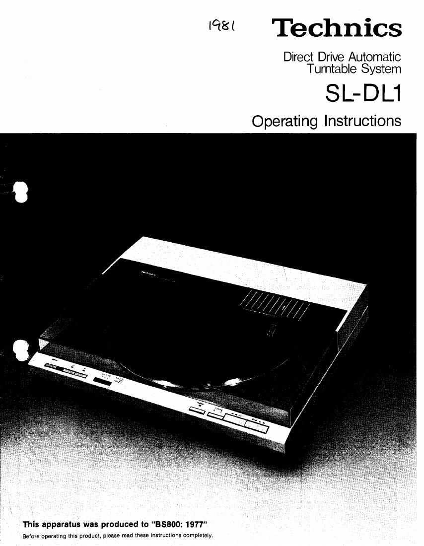
Technics SLD l1 Owners Manual
This is the 14 pages manual for Technics SLD l1 Owners Manual.
Read or download the pdf for free. If you want to contribute, please upload pdfs to audioservicemanuals.wetransfer.com.

Extracted text from Technics SLD l1 Owners Manual (Ocr-read)
Page 1
Technics
Direct ve Automatic
Turntable System
SL-DL1
Operating Instructions
This apparatus was produced to 38800: 1977
Before operating this product, please read these instructions completely,
Page 2
We want to thank you for selecting the SL-DLl.
For optimum performance, we recommend that you read these instructions carefully.
Caution for safe use
of this apparatus
(For UNITED KINGDOM)
Caution
o This apparatus isdoubie insulated safely earth not required.
important
0 The wires in this mains lead are coloured In accordance with
the tollowlng code:
Blue: Neutral
Brown: lee
As the coloursoltho wires in themains lead of thisapparatus
may not correspond with the coloured markings identifying
the terminals in your plug, proceed as follows.
The Wlie which is coloured BLUE must be connected to the
terminal which is marked with the letter N or coloured
BLACK, The wire which is coloured BROWN must be con-
nected to the terminal which is marked with the letter L or
coloured RED.
This equipment should be disconnected trom the mains
when not In use.
Before use
This unit is shipped with packing material and spacers
attached to protect it during transport. some parts are
not mounted on the unit and are packed separately.
Please read these instructions carefully before use.
I Removing the packing material
1. Pull oft the tonearm protection spacer.(Fig. 1)
Be careful not to touch the stylus.
2, Remova tape on side of cartridge (This prevents the
stylus assembly from shaking loose during shipment.)
I Contents
Turntable unit ..
Turntable platter ,
Turntable mat ........
45-rpm adaptor ....................................... l
l installation at turntable platter
1. Place the turntable platter on the center spindle. (Fig.2)
Put your fingers through the two holes in the platter.
and line them up with the two recesses underneath.
Follow the reverse procedure if it is necessary to remove
the platter.
Note:
The rotor is connected to the underside of the turntable
platter. (The magnet of the motor is attached to the turn-
table platter.) To maintain optimum performance, extra
care should be taken to preventadhesmn of dust or iron
filings to the magnet and not. to damage the magnet by
dropping it.
Do not remove or loosen the screws, Should the position
of the tixed magnet be altered by loosening the securing
screws, the rated performance otthe unitcannot beguar-
anteed. (Fig. 3)
2. Place the turntable mat on the platter, (Fig. 4)
Line up the protrusions in the turntable mat with the
recesses in the platter (at two places as shown).
Connections
I Connect the output terminals (Fig.5)
Output terminals Amplifier or Receiver
L (White)-> -Channel
R (Red)---9 Channel
GND (Spade lug)-> HIE]
Note:
Always Connect the ground cord to the GNU terminal on
your amp or receiver to prevent hum
Connect the AC power plug
Connect the AC power plug to an AC wall socket.
Caution:
Make sure that the turntables AC line-voltage selector is
matched to your local voltage betore connecting the AC
power plug (Fig. 5)
Never connect to a DC socket. .
If the pro-selected voltage is diflerent from your local
voltage. turn the AC line-voltage selector with a screw-
driver so that it corresponds to your local voltage.
The AC Iinevoltage selector is located at the-bottom of
the base.
Placement
Place the unit in a stable and horizontal position where there
is littlp or no vibration.
Place the unit away from the speakers so that it will be
subiect to as little direct sound radiation as possible.
Do not use or store this unit where it will be exposed todust.
dirt, high humidity or high temperature. Do not place it near
heaters.
Place it in a well ventilated location.
Do not use under direct sunlight. spotlights, or other ex-
tremely bright light sources.
Bright lights may cause misoperation of the optical sensor
system and therefore interference with automatic operation.
This also applies to flashlights or infrared remote control
units brought very close to the turntable.
Do not place it near or on top of a power amplifier, since
power amps radiate much heat.
Place the turntable away Irom the power amp to prevent
hum.
Hum may be caused by leakage flux from the transformer in
the power amplitler (or integrated amp). Therefore. it you
notice hum, try moving the turntable to a slightly different
location. further away from the amp.
If you try to listen to a radio near the turntable while it is
turning, you may hear some interference.
Page 3
.// ..*
Tonearm
protection spacer
,
diac she
m 1- )
25mm
mm,
0
1O
Securing
l
5 m__
Ground wire to
,7, /Phono terminals
SELECT
LINE VOL TAGE
(G N D) «1: K
g} ( 110-4sz
(I)
13
16
Stylus-pressure
_n+
adiustment screw