Technics RSM 273 Service Manual

This is the 40 pages manual for Technics RSM 273 Service Manual.
Read or download the pdf for free. If you want to contribute, please upload pdfs to audioservicemanuals.wetransfer.com.

Page: 1 / 40
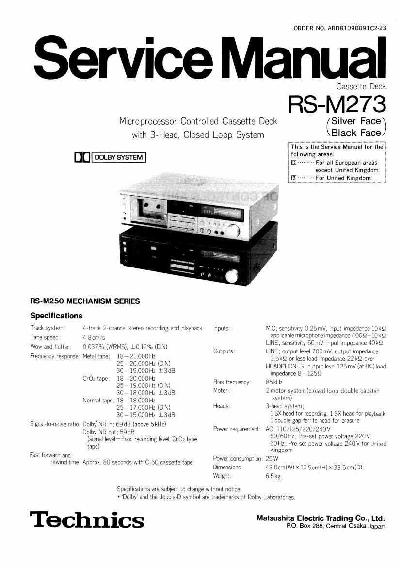
Technics RSM 273 Service Manual

Extracted text from Technics RSM 273 Service Manual (Ocr-read)


Page 1

ORDER NO. ARD81090091C2-23

ervice Manual

Cassette Deck

RS-M273

Microprocessor Controlled Cassette Deck (Silver Face)

with 3-Head, Closed Loop System

on-

RS-M250 MECHANISM SERIES

Specifications
Track system 4rtrack Zechannel stereo recording and playback inputs
Tape speed 4 8cm/s

Wow and flutter 0 037% (WRMS), i0.12% (DIN)

Frequency response Metal tape, 18 - 21,000 Hz
257 20,000 Hz (DIN)
30719,000Hz :3dB
CrO; tape, 18 - 20,000 Hz
257 19,000 Hz (DIN)

Outputs

Bias trequency'

30718,000Hz :3dB Motor.
Normal tape; 18718,000Hz
25717,000Hz (DIN) Heads:

30715000Hz i3dB
SignalrtO-noise ratio: DolbyNR in, 69 dB (above BkHz)
Dolby NR out, 59dB
(Signal level:max recording level, 002 type
tape)

Power requirement

Fast forward and

rewmd time Approx 80 seconds With C760 cassette tape Power consumption

DimenSIons.
Waight:

Specrtications are subject to change without notice

Black Face

This is the Service Manual for the

following areas.

IE ------- For all European areas
except United Kingdom.

[Elm ---For United Kingdom.


MIC. sensitivity 0 25mV, input impedance 10 ks:
applicable microphone impedance 40052710k£2
LINE; senSItIVIty 60 mV, input impedance 40kt!
LINE; output level 700 mV, output impedance
3 5kS2 or less load impedance ZZkQ over
HEADPHONES: output level 125 mV (at 8&2) load
impedance 8712582
85 kHz
27motor system (closed loop double capstan
system)
3rbead system,
1 8X head for recording, 1 SX head for playback
1 doublergap territe head tor erasure
AC, 110/125/220/24OV
50/60 Hz; Preset power voltage 220V
50 Hz; Preset power voltage 240V for United
Kingdom
25W
43 0cm(W) X 10 9cm(l-l) X 33 5cm(D)
6.5kg

* Dolby and the doubleeD symbol are trademarks of Dolby Laboratories

Te ChniCS Malsushita Electric Trading Co., Ltd.
PO. Box 288, Central Osaka Japan

Page 2

RS-M273

CONTENTS

ITEM PAGE
LOCATION OF CONTROLS AND COMPONENTS 1


DISASSEMBLY INSTRUCTIONS ----------- 2
CHIP PARTS REPAIR PROCEDURE 3
TECHNICAL EXPLANATION ----------------- - 3
MEASUREMENT AND ADJUSTMENT METHODS 4
MN14OORZ(IC601): EACH TERMINAL

FUNCTION AND WAVEFORM --------------------- 12
TROUBLESHOOTING OF MAIN CONTROL

CIRCUIT ..................................................... 15
ELECTRICAL PARTS LOCATIONH- 18
BLOCK DIAGRAM ....................... .. 18
SCHEMATIC DIAGRAM

(MAIN SECTION/FL METER SECTION) ---------- 19

ITEM PAGE
CIRCUIT BOARDS

(MAIN CIRCUIT BOARD/FL METER

CIRCUIT BOARD) ....................................... 20
SCHEMATIC DIAGRAM

(MAIN CONTROL SECTION) ------------------------ 21
CIRCUIT BOARD

(MAIN CONTROL CIRCUIT BOARD) -------------- 21
WIRING CONNECTION DIAGRAM ---------------------- 22
MECHANICAL PARTS LOCATION ----------------------- 23

BELT LOCATION ................. 1.24

CABINET PARTS LOCATION ~


LOCATION OF CONTROLS AND COMPONENTS

(39

(PI

\/ ®

//////////////IIIIIIIII IIII

@EO

A
\4/


©®
@

18 725 ,
IIIIIII IIII III IIII
IIIIIII IIIIIIIIIIIIIIIIIIIIIII I
m [,1 [7] ] III 1 I
31) 3I 32 (33/1

(L Cassette hoIder 1); Record button and IndIcator [rec (O)
(2/ Auto tape seIect IndIcators [ATS (Normat ~ CrOv - Metat)j 19, RewInd button [rew (44)]
3, Tape monttor source IndIcator [source] 20, Stop button [stop (I)]
(44 Three head IndIcator I?!» Pause button and IndIcator [pause (II)]
3/ MonItor tape IndIcator [tape] IZZ PIaybaCA button and IndICator [pIay (>)]
(Q: Dotby NR IndIcator [DoIby NR] 33 Reset button [counter reset]
(7, Record nIutIng SWItch [rec rnute (0)] 21; Fast forward button [It (>>)]
(LL Memory stop posItIon IndIcator [memory] (2; MonItor SWItCh [monrtor ( - source - 1 tape)]
(9/ Repeat poSItIon IndIcator [repeat] (26) BIas trne adjustment controI [bIas adjust]
L0» DIgItaI eIeCtronIC counter [eIectrOnIc counter] E7) DoIby NR SWItCh [DOIby NR (In - out)]
ll Eject button [eject] (8 Output IeveI controI [output IeveI]
12/ Power SWItCh [power (push on)] @I MIcropnone Jacks [mIC (L . R)]
(13, TImer start SWItch [I tInIer (rec . ofi - ptay)] 33 LIne output [aCkS [LINE OUT (L - R)]
(14/ Headphones [aCk [phones] 131/ LIne Input [3ka [LINE IN (L - R]]
15 FL (fluorescent IeveI) rneter L32 Rernote controI connector [REMOTE CONTROL]
([6; Memory SWItch [memory (stop - OI'I - 'epeat)] (337 Voltage seIeCtor [VOLTAGE SELECTOR]

(17/ Input IeveI controIs [Input IeveI (L-QRH

Page 8

-M273 RS-M273

MEASUREMENT AND ADJUSTMENT METHODS

Tape selector (Tape mode switching)

For measurement adjustment With test tapes Without tape detection
holes (A and B): sWitch tape modes as follows.

(For normal tape mode. just insert a normal tape into the cassette

holder)

* Metal tape mode setting:
Metal tape mode is obtained by disconnecting the 3 pin socket

trom the 3 pin post

* CrOz tape mode setting:
FIVST disconnect the 3 pin socket ll'l the same way as above,
Then, as illustrated in the figure right, connect the terminal-3 of

<-3 pin socket-

Connection

on the P C B (Printed Circuit Board)

the 3 pin post to the ground With a connection Wire

ADJUSTMENT PARTS LOCATION

Ram

/T PT7TTFTSTTP8\ "

@202 t

\ R203 L106 \
\


i- iiiiiiiiiii 1| =~ - . - /'\ [Ema
>Tape speed I I \ - I

i adjustment VR I

l l

: Capstan moter i

l R143
l

i

i

l

L ,,,,,,,,,, u

/ / ,4
L105 VR202 VR201 VR203I/ \
I

\ll

\

Fig. 1

NOTE: Set lever SWitches and controls in the following positions, unless otherWise specified

O Make sure heads are clean

0 Make sure capstan and

O Judgeable room temperature: 20i5C (68i9F)

0 Monitor selector Tape

0 Bias adjustment control. Center

I Input level controls Maximum
0 Output level control' Maximum.
0 Dolby NR selector Out.

0 input selector Line

U Timer selector OFF

- Menory selector. OFF

pressure roller are clean

ITEM

MEASUREMENT & ADJUSTMENT

0 Pressure of pressure
roller

Condition

' Playback mode

Equment

~ TenSion gauge (max 500 gr)

Place UNIT into playback mode

Hook tenSIOn gauge to pressure roller shaft top (A): and pull gauge in direction oppOSite to pressure
of pressure roller against capstan (See fig 2)

3 Read pressure indicated on gauge immediately when pressure roller moves away from capstan and
stops rotating

M...

CIDSII"

. Pressure roller

_ (A) (A)
Supply side Fig. 2

Ta ke»up side

Standard value: 130 tZOgr Standard value: 350:50gr

® Takeup tension

Condition

- Playback mode

Equipment

. Cassette torque meter
(szstCT)

H

Mount cassette torque meter on UNIT
2 Place UNIT into playback mode

IL Standard value: flotiggr-cm

9 Tape speed

Condition

a Playback mode

1 Normal tape mode
Equment

* Digital electronic counter
' Test tape QZZCWAT

Tape speed accuracy

1 Test equipment connection is shown in fig 3.

2 Playback test tape (QZZCWAT 3000 Hz): and supply Remm/pjayback hm urts out :1
playback Signal to frequency counter E DIED

3. Take measurement at middle section of tape , O

4 Measure this frequency Dlgltal elecllic counter

5 On the baSis of 3000 Hz: determine value by tollowrng Fig 3

f0mleZpe speed accuracy * :33000
3000

where t: measured value

i1t5%

Standard valu
,

Test tape Playback mode

x 100 l%)

Adjustment method

I Playback the test tape (middle)
2 Adjust so that trequency becomes 3000 Hz
3 Tape speed adjustment VR shown in fig 1

Tape speed fluctuation
Make measurements in same manner as above (beginning: middle and end oi tape) and determine the
dil'lerence between maximum and minimum values and calculate as follows

r. er:
3,000 x1000 l%)

tr 7 maximum value, t; : minimum value

Standard value: Less than 1.0%

Tape speed tluctuation 4

@ Input scanning time
adjustment

Condition

. Stop mode

Equipment

. Oscilloscope

I Connect osolloscope to G7] terminal of lC60l
2 Measure the time of input scanning signal With oscilloscope as shown in fig 4

| Standard value: 5msec-6.25msec

3 It the measured value is markedly different from the Signal shown below make the necessary adjust


ment as follows t,
w Oscilloscope
'.-l C
l C3 >
Smsec - 5,25 msec we;

Fig. 4

Page 20

RS-M27

Terminal Symbol Name Function/operation
38. D07 No connection Not used.
39. VDD Power source Operated at 4.5V to 6.0V.
40. 056 Oscillation terminal

3H is---

us

Oscillation is approx. 300kHz. Because the connection of a
probe affects the terminal, nothing should be connected to
this terminal for any other measurements

Use 00¢ to 3 in measuring the computers velocity; Approx.
155 Hz in STOP condition.

TROUBLESHOOTING OF MAIN CONTROL CIRCUIT

Microcomputer Relevant Relevant
Fault Probable cause terminal to mechanism external
check parts parts
Mechanism dose not
operate at all.
FL notiighting Microcomputer not
operating
Power not supplied. 39 (VDD)
Clock not oscillating. 40 (080 0604, R613 to
10 to 13 615
Reset locked. 27 (RST) 0606,D606,Q217,
lC605
Microcomputer normal,
(Scan normal)
Connection to FL Driver. 10 to 13
31 to 37
FL lighting OK. Half SW. closed. 14 (Ai3) Halt SW. 0603
(MODE LED not lighting.)
MODE indicator lighting Motor circuit faulty. 24, 25 Motor |C602
OK. connection