Sony xm 502 z owners manual
This is the 4 pages manual for sony xm 502 z owners manual.
Read or download the pdf for free.
If you want to contribute, please mail your pdfs to info@audioservicemanuals.com.

Extracted text from sony xm 502 z owners manual (Ocr-read)
Page 1
Specifications
AUDIO POWER SPECIFICATIONS
POWER OUTPUT AND TOTAL HARMONIC DISTORTION
50 watts per channel minimum continuous average power into 4 ohms,
both channels driven from 20 Hz to 20 kHz with no more than 0.04% total
harmonic distortion per Car Audio Ad Hoc Committee standards.
Other Specifications
Circuit system OTL (output transformerless) circuit
Pulse power supply
Inputs RCA pin jacks
High level input connector
0.3 - 6 V (RCA pin jacks),
1.2 - 12 V (High level input)
Out-puts Speaker terminals
Speaker impedance 2 7 8 9 (stereo)
4 7 8 Q (when used as a bridging amplifier)
100W X2(at4Q)
Input level adjustment range
Maximum output
-
Especi icaciones
Sistema de circuito Circuito OTL (salida sin transforrnador)
Suministro de alimentacion por impulsos
Entradas Tomas con terminales RCA
Conector de entrada de alto nivel
Margen de ajuste de nivel de entrada de 0,3 a 6 V (tomas con terminales RCA),
de 1,2 a 12 V (entrada de alto nivel)
Salidas Terminales de altavoz
lmpedancia de altavoz de 2 a 8 Q (estéreo)
de 4 a 8 (2 (Si se utiliza como amplificador en puente)
100 W X 2 (a 4 Q)
250 W (BTL, a 4 Q)
Salida nominal (tension de Suministro a 14,4 V)
50 W X 2 (de 20 Hz a 20 kHz, 0,04 "0 Tl-lD, a 4 S2)
60 W X 2 (de 20 Hz a 20 kHz, 0,1 /9 THD, a 2 Q)
120 W (monoaural) (de 20 Hz a 20 kHz, 0,1 "0 THD, a 4 9)
de 5 Hz a 80 kHz :3 dB)
0,005 % o inferior (a 1 kHz, 4 Q, a 10 W)
Salida maxima
Respuesta de frecuencia
Distorsion armonica
Filtro de paso bajo 80 Hz, -18 dB/oct
Requisitos de alimentacion Bateria de automovil de cc de 12 V (negativo a masa)
Tension de suministro de alimentacion de 10,5 a 16 V
250 W (BTL, at 4 Q)
Rated output (supply voltage at 14.4 V) 50 W X 2 (20 Hz - 20 kHz, 0.04 o THD, at 4 Q)
60 W X 2 (20 Hz - 20 kHz, 0.1 "o THD, at 2 Q)
120 W (Monaural) (20 Hz - 20 kHz, 0.1 "a THD, at 4 (2)
Frequency response
Harmonic distortion
Low-pass filter
Power requirements
Power supply voltage
Current drain
5 Hz - Suki-12 ( *3 dB)
0.005 "/a or less (at 1 kHz, 4 Q, 10 W)
80 Hz, 718 dB/oct
12 V DC car battery (negative ground)
10.5 - 16 V
at rated output: 15 A (4 Q, 50 W X 2)
Remote input: 1 mA
Dimensions Approx. 262 X 53.5 X 173 mm (10 3/3 X 21/3 X 6 7/3 in.) (w/h/d)
not incl. projecting parts and controls
Mass Approx. 1.9 kg (4 lb. 4 oz.) not incl. accessories
Supplied accessories
Mounting screws (4)
High level input cord (1)
Protection cap (1)
Design and specifications are subject to change without notice.
Features
I Maximum power output of 100 watts per
channel (at 4 Q).
I This unit can be used as a monaural amplifier
with a maximum output of 250 watts.
I Dual mode connection possible for a multi-
speaker system.
I Built in Low7pas. filter (80 Hz, 718 dB/oct).
I Built in protection circuit".
I Pulse power supplyM for stable and
regulated output poweri
I Direct connection can be made with the
speaker output of your car audio if it is not
equipped with the line output (High level
input connection).
* Protection circuit
Thisamplifier is provided With a protection
circuit that operates in the following cases:
7 when the unit is overheated
7 when a DC current is generated
7 when the speaker terminals are short
circuited.
The color of the POWER/PROTECTOR indicator
Will change from green to red, and the unit Will
shut doWn.
If thishappens, turn off the connected
equipment, take out the ca§ette tape or disc,
and determine the cause of the malfunccion. If
the amplifier has overheated, wait until the unit
cools down before use.
** Pulse power supply
This unit hasa built-in power regulator which
converts the power supplied by the 12 V DC car
battery into high speed pulses using a
semiconductor switch. These pulses are szepped
up by the built-in pulse transformer and
separated into both positive and negative power
supplies before being converted into direct
current again. This isto regulate fluctuating
voltage from the car battery. This light weight
power supply system provides a highly efficient
power supply with a low impedance output.
POWER/PROTECTOR indicator
Installation
Before Installation
I Mount the unit either inside the trunk or
under a seat.
I Choose the mounting location carefully so the
unit will not interfere with the normal
movements of the driver and it will not be
exposed to direct sunlight or hot air from the
heater.
I Do not install the unit under the floor carpet,
where the heat dissipation from the unit will
be considerably impaired.
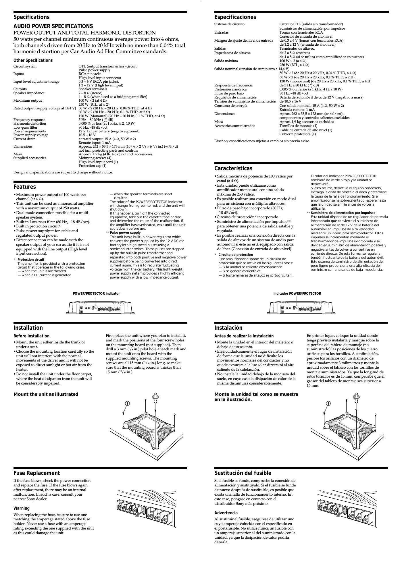
Mount the unit as illustmted
Fuse Replacement
If the fuse blows, check the power connection
and replace the fuse. If the fuse blows again
after replacement, there may be an internal
malfunction. In such a case, consult your
nearest Sony dealer.
Warning
When replacing the fuse, be sure to use one
matching the amperage stated above the fuse
holder. Never use a fuse with an amperage
rating exceeding the one supplied with the unit
as this could damage the unit.
First, place the unit where you plan to install it,
and mark the positions of the four screw holes
on the mounting board (not supplied). Then
drill a 3 mm (/x in.) pilot hole at each mark and
mount the unit onto the board with the
supplied mounting screws. The mounting
screws are all 15 mm (/32 in.) long, so make
sure that the mounting board is thicker than
15 mm (/32 in.).
Consumo de energia
Con salida nominal: 15 A (4 Q, 50 W X 2)
Entrada remota: 1 mA
Dimensiones Aprox. 262 X 53,5 x 173 mm (an / al / prf),
componentes y controles salientes excluidos
Masa Aprox. 1,9 kg accesorios excluidos
Accesorios suministrados
Tornillos de montaje (4)
Cable de entrada de alto nivel (1)
Cubierta protectora (1)
Disefio y especificaciones sujetos a cambios sin previo aviso.
Caracteristicas
I Salida maxima de potencia de 100 vatios por
canal (a 4 Q).
I Esta unidad puede utilizarse como
amplificador monoaural con una salida
maxima de 250 vatios.
IEs posible realizar una conexion en modo dual
para no sistema con multiples altavoces.
I Filtro de paso bajo incorporado (80 Hz,
718 dB/ oct).
ICircuito de proteccion* incorporado.
I Suministro de alimentacion por impulsos
para obtener una potencia de salida estable y
regulada.
I Es posible realizar una conexion directa con la
salida de altavoz de un sistema de audio para
automovil si éste no esta equipado con salida
de linea (Conexion de entrada de alto nivel).
* Circuito de proteccion
Esze amplificadordispone de un circuito de
proteccion que se activa en los siguientes oasos
7 Si la unidad se calienta excesivamente
7 Si se genera corriente cc
7 Si los terminales de altavoz se cortoci rcuitan.
El color del indicador POWER/PROTECTOR
cambiara de verde a rojo y la unidad se
desactivara.
Si esto ocurre, desactive el equipo conectado,
extraiga 1a cinta de casete o el disco y determine
la causa de la falla defuncionamiento. Si el
amplifioador se ha sobrecalentado, espere hasta
que la unidad se enfrie antesde volver a
utilizarla.
6 Suministro de alimentacién por impulsos
Esta unidad dispone de un regulador de potencia
incorporado que convierte el suminiszro de
alimentacion de cc de 12 V de la baterla del
automévil en impulsosde alta velocidad
mediante un interruptor semiconductor. Estes
impulsosse incrementan mediante el
transformador de impulses incorporado y se
diViden en suministro de alimentacion positiva y
negativa antes de volver a convertirse en
corriente directa. De esta forma, se regula la
tension fluctuante de la bateria del automovil.
Este sistema de suministro de alimentacion de
peso ligero proporciona una alta eficacia del
suminisro con una Elida de baja impedancia.
lndioador POWER/PROTECTOR
Instalacion
Antes de realizar la instalacion
I Monte la unidad en el interior del maletero o
debajo de un asiento.
I Elija cuidadosamente el lugar de instalacion
de forma que la unidad no diticulte los
movimientos normales del conductor y no
quede expuesta a la luz solar directa ni al aire
caliente de la calefaccion.
I No instale la unidad debajo de la moqueta del
suelo, en cuyo caso la disipacién de calor de la
misma disminuira considerablemente.
Monte la unidad tal como se muestra
en la ilustracién.
En primer lugar, coloque la unidad donde
tenga previsto instalarla y marque sobre la
superficie del tablero de montaje (no
suministrado) las posiciones de los cuatro
orificios para los tornillos. A continuacion,
perfore los orificios con un diametro de
aproximadamente 3 milimetros y monte la
unidad sobre el tablero con los tornillos de
montaje suministrados. Ya que la longitud de
estos tornillos es de 15 mm, compruebe que el
grosor del tablero de montaje sea superior a
15 mm.
Sustituci n del fusible
Si el fusible se funde, compruebe la conexion de
alimentacion y sustituyalo. Si el fusible se funde
de nuevo después de sustituirlo, es posible que
exista una falla de funcionamiento interno. En
este caso, pongase en contacto con el
distribuidor Sony mas proximo.
Advertencia
Al sustituir el fusible, asegurese de utilizar uno
cuyo amperaje coincida con el especificado en
el portafusible. No utilice nunca un fusible con
un amperaje superior al del suministrado con la
unidad, ya que la disipacion de calor podria
danarla.
Page 2
Troubleshooting guide
The following checklist will assist in the correction of most problems which you may
encounter with your unit.
Before going through the checklist below, refer to the connection and operating
procedures.
Problem Cause/Solution
The POWER/PROTECTOR The fuse is blown.
indicator does not light -> Replace the fuse with a new one.
up.
The ground wire is not securely connected.
-> Fasten the ground wire securely to a metal point of the
cart
The voltage going into the remote terminal is too low.
0The connected master unit is not turned on.
-e Turn on the master unit.
0The system employs too many amplifiers.
-> Use a relay.
Check the battery voltage (105 - 16 V).
'The POWER/PROTECTOR Use speakers with suitable impedance.
indicator will change OStereo operation: 2 - 8 Q
from green to red. OBridging operation: 4 - 8 Q
-The unit becomes
abnormally hot.
The speaker outputs are short-circuited.
-> Rectify the cause of the short-circuit.
Alternator noise is heard. The power connecting wires are installed too close to the
RCA pin cords,
-> Keep the wires away from the cords.
The ground wire is not securely connected.
-> Fasten the ground wire securely to a metal point of the
Carl
Speaker wires are touching the car chassisl
-> Keep the wires away from the car chassisl
-
Guia de solucion de problemas
La siguiente lista 1e resultara util para solucionar la mayoria de los problemas que pueda
encontrar con la unidad.
Antes de consultar la lista, examine los procedimientos de conexion y funcionamiento.
Problema Causa/Solucién
El indicador POWER] El fusible se ha fundido,
PROTECTOR no se ilumina. -> Sustitllyalo por otro nuevo.
El cable de toma a tierra no esta firmemente conectado.
-> Conéctelo firmemente a un punto metalico del
automovil.
La tension que recibe el terminal remoto es demasiado baja.
ONo ha activado la unidad principal conectada.
-> Activela.
0E1 sistema emplea demasiados amplificadores.
-> Utilice un relé.
Compruebe la tension de la bateria (de 10,5 a 16 V)
° El indicador POWER] Emplee altavoces con una impedancia adecuada.
PROTECTOR cambia de OFuncionamiento estereo: de 2 a 8 Q
verde a rojo. OFuncionamiento en puente: de 4 a 8 Q
- La unidad 5e calienta de
forma anormal.
Las salidas de altavoz estan cortocircujtadas,
-> Rectifique la causa del cortocircuito,
Se escucha ruido del Los cables de conexion de alimentacion se encuentran
altemador. demasiado cerca de los cables con terminales RCA.
-> Mantengalos alejados entre si,
El cable de toma a tierra no esta firmemente conectado.
-> Conectelo firmemente a un punto metalico del
automovil.
Los cables del altavoz han entrado en contacto con el chasis
del automovil.
-> Manténgalos alejados del chasis.
3-263-305-12 (1)
SONX.
Stereo Power
Amplifier
Operating instructions
Manual de instrucciones
Owner's Record
The model and serial numbers are located on the bottom of the unit.
Record the serial number in the space provided below.
Reter to these numbers whenever you call upon your Sony dealer regarding this product.
Model No. XM-SOZZ Serial No.
XM -5022
@2004 Sony Corporation Printed in China
Parts for Installation and Connections
Componentes de instalacion y conexiones
6) ® ®
1
B 5 X 15
(x 4)
Dimensions
Dimensiones . .
Unit: mm (111.)
Unidad: mm
286.8 (11 3In)
53.5 V
(2 la) 262 (10 3In)
l
.. -
g s
l
262 (10 3/3)
- Halogenated flame retardants are not used in printed wiring boards.
- Halogenated flame retardants are not used in cabinets.
. Corrugated cardboard is used for the packaging cushions.
http://www.sony.net/