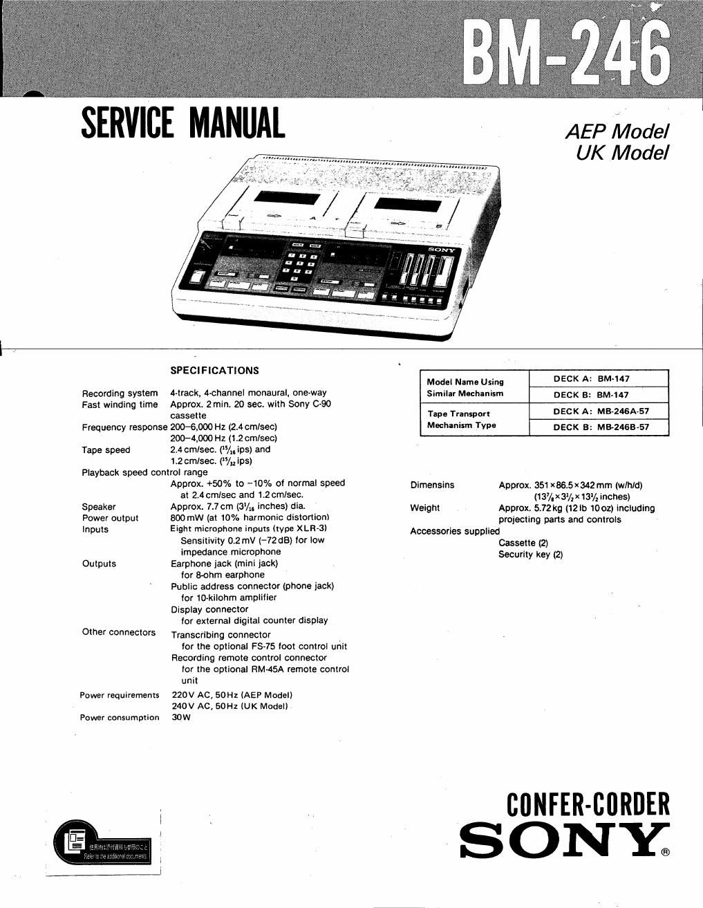
Sony bm 246 service manual
This is the 56 pages manual for sony bm 246 service manual.
Read or download the pdf for free. If you want to contribute, please upload pdfs to audioservicemanuals.wetransfer.com.
Extracted text from sony bm 246 service manual (Ocr-read)
Page 2
BM-246 '
FEATURES
Specially designed tor recording courtroom proceedings,
conferences or meetings
Dualdeck conter-corder
With the AUTO CHANGE switch 0N, long uninterrupted
recording is possible Before the end at tape on deck A (8),
recording on deck 8 (A) starts automatically.
\Nlth the AUTO CHANGE switch OFF, both decks A and B
can be opemted simultaneously or separately.
Ltraclc 4channel recording system
Eight microphone inputs into Iour channels can be
recorded simultaneously. (The sound input lrorn two
microphones is mixed and recorded on one channel.)
Any channel or all can be selected Ior monltoring.
Search Iunctions
A particular recorded segment of the tape can be quickly
located and the end of the last recorded segment on the
tape can easily be located.
Fail-sate warning system
Alarm sound and indication on the counter display prevent
recording errors
Recorded cassette protection
Built-in circuitry makes it impossible to record over a
recorded segment on the cassette
Digital tape counter and alarm indicator
The tape position («Sign readout 0000 to 9999) cassette
number (1, Z 3, etc.) during continuous recording and alarm
Indication appear for easy reference.
Transcriblng capability
With the use ol the optional F575 toot control unit, deck B
car he used Ior transcribing.
Recording or telephone calls
With the use at the optional RDl»246 telephone interface,
up to tour telephone lines can be connected lor long
uninterrupted recording 0! calls.
Public address and display jacks
A PA (public address) jack and DISPLAY connector (for
optlonal remote dlsplay) are provided.
Security key look
A security key locks the cassette holders of both decks A
and Br
TABLE OF CONTENTS
Section Title Page
Specifications ........................ 1
Features ............................ 2
Servicing Note ........................ 3
SECTION 1. GENERAL ................ 4
1-1. Location and Function of Controls . . I t 4
1-2. Recording ..................... 5
1-3. Tape Playback .................. 6
1-4. Public Address .................. 6
1-5. Search Function ................. 7
1-6. Information Display .............. 7
1-7. Alarm System .................. 7
l-8. Transcribing ................... 8
1-9. Remote Control Operation ......... 8
Section Title Page
SECTION 2. OUTLINE ................. 9
2-1. IC901(uPD75108CW-151)
Pin Functions ................. 9
2-2. IC901 (uPD75108CW-151)
Output Port and Mode ............ l 1
2-3. Serial Signal ................... 13
2-4. Communication with RDI246 ...... 14
2-51 Fluorescent Display Drive (Dynamic) . . 15
2-6. Detectors of Take-up Reel and
Supply Reel Signals .............. 16
2-7. On the Key Matrix .............. I7
SECTION 3. DISASSEMBLY ............ 18
SECTION 4. MECHANICAL ADJUSTMENT . 20
4-1. Torque Measurement ............. 20
4-2, Tape Path Adjustment ............ 20
4-3. Rotor Thrust Adjustment .......... 20
4-4. Forward-Solenoid Position Adjustment . 21
4-5. F/ R (F ast-Forward/ Rewind)
Solenoid Position Adjustment ....... 21
SECTION 5. ELECTRICAL ADJUSTMENT . . 22
5-1. Tape Speed Adjustment ........... 22
5-21 Motor Output Level Adjustment ..... 22
5-3. Record/Playback Head Azimuth
Adjustment ....... ............ 23
5-4 Monitor Head Azimuth Adjustment . . I 23
5-5. Tape Monitor Level Adjustment ..... 24
5-6. Frequency Responce Check and
Record Bias Adjustment .......... 24
5-7. Record Inhibit Azimuth Adjustment . I 25
SECTION 6. DIAGRAMS .............. 26
6-1. Circuit Boards Location ........... 26
6-2. Block Diagram ................. 27
6-3. Printed Wiring Boards (1)
Servo Control Section ........... 30
64 Schematic Diagram (1)
Servo Control Section ........... 33
6-5. Semiconductors Lead Layouts ...... 39
66. Printed Wiring Boards (2)
Audio Section ................ 41
6-7. Schematic Diagram
Audio Section ................ 43
SECTION 7. EXPLODED VIEWS ......... 47
SECTION 8. ELECTRICAL PARTS LIST. . . 52