Philips 747 service manual
This is the 3 pages manual for philips 747 service manual.
Read or download the pdf for free.
If you want to contribute, please mail your pdfs to info@audioservicemanuals.com.

Extracted text from philips 747 service manual (Ocr-read)
Page 1
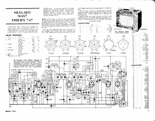
MULLARD
MAS7
PHILIPS 747
50-100 cyrlej. A (unwrtor unit mar be [mun]
making the instrument immblc jizr operation
from DC as V]! m AC mama. Mar/mm! by
Mil/lard W Elms Slfl'iCl (0.. L111.. 11111!
Phi/[171 Lam/7.1. LII/.1 Ccmm) Home, S/mfnbun
Arc/1111, London, WC2.
VlHE aerial inpul is fed via Ihc wane-change
swuch to (he aperiodic coil L7 (MW) which is
10 1; single tuned circuit comprising L13, mned by 1ch meme
C10.
An 1F filler circuit is inc6rporaxed between
aerial and earth and comprises L6, tuned by the
trimmer C12. Image suppression is eficcied by
C13 and C22.
Signals from the tuned circuils are fed 10 (he
control grid of an anode frequency~chungen V1.
which is cumodc biased by R7 and RS. dccnuplcd
Conunucd nurlea!
coupled inductive? and also by L29 and C23 10
the primary. L9, 0 1hc bundpuw filler. (91uncs
Ihe primary and 1h: circuit is coupled by L30 and CAPACITORS
Faun-111w. plm m-Iifirr am/ zulhmlp»m_1- C2510 the secandary circun of the finer. L11 tuned .. (mu, , v.1": .. f, 7, . Y '11 ,
riirml mun. three wawb/uml .mpn/ml, A hy (10. 1 32 7 00114
mums nmul rlL'vlrr ix prov/(mi mrr/ NU"A(I\ for On Lw the addm , . . 2 I? 22 :0 mm (Nrcrr {MW
1 . , , oml coils L15, Lin and L12 . , WL'JFCNANCE i
ll ll'shjllilflzilu"
extra .spul 1/. or A [mu/1.1 100-.50 min, C24. SW signals arc fed from the atrial nu C41 6 32 lg 025 The, Hugh}?! MASI wmm.
Vernon 13 t e receiver WW
ALVE READINGS
1'1,» r 11ml. V 6
1 F01 ., Anoué ,W A
05:: Anode ,. ,
Screen 30 . . 5,4 mmfd
('Allhodc 31 1
2 \P48 .. ., Anode F F 12 . .
Screen 3.1 .. . 0 05
(Zuhode 34 , , . 250 mmfd
1 mm ., Anuhue T~A- 35 ., .. .05
(.11 ode 36 ., .1 20 mmrd.
J i-FNADD .. Anudc .17 .. ., 50 mmfd
Sérccn . TARGET A 121 ,, 040 11312110
rxd . , 1 . 39 , .
s TV4 .. .. '1 unmglndlcumr 40 . .. .0001
0 W2 .. ,. Reclilicr PEN4DD T V4 DWZ 41 . .. 10mm
* lcusurul 11mm R25 4: . ., .002
4.1 ,. .. 125
R1 P U C 4 9 44 ., . 0005
A (our-vans. plus reuifier. sunerhet var 5 ,. ' '2?
Ac operiuan. the receiver employs a 7 ' ' H0 riuu
cathoge-ray typ! tuning indium". Three R58 an L5 3 - -' " "1
wave ands are covered, and the circuit is ' '
A (mama: 555122" a mm an... R2 R55 R36 ~ RSI-26 L27 49 ~ ~ E
men: 0 eaye and for a negative
(«muck circuit for tone improvement. C5 . RESISTORS )1
R ( mm
1" ' V 7. 23110600
41 C4 2 , 2 x 10.000
\ .0 5 1000131121
. s
. D 7 250
1 s . ,, 10.000
~' 9 ,, . 50,000
10 . . 400
11 . , . 2 meg
12 .. .. 250.000
13 - ,. 500,000
14 . . . . 5 mag
15 H ,, 1.6 mag
10 H . 1.6 meg
17 . , 20
18 ., . 3,200
21 .. ., 9 meg
22 .. .. 100.000
2.1 r. ., 1100.000
24 ,, . 10.000
25 . 125
20 320
27 50
28 500,000
29 500,000
30 600,000
31 .
L4 32 320.000
2 13 1 mg
34 211135
11.01 LAM s g: 330""
~ 37 I 1601000
38 g f . 100,
lunch 1 946 111
Page 2
MULLARD
TUNERlN/Vfi'
VOLUME 0N~0FF «were
GE ours»: TONE CONTR OLloL/rs/Q In}
MAS7 [DIWAVECHAN
(umlmlell - C 9
ClO
cu
.@
MA/NS AER/AL xw
E
These two diagrams
identify the parts both
an to): and underneath
the chassis. HF wires
are bare. and care
should be taken not
to displace them.
Where they approach
each other. there
should be It least
ml inch clearance
W59
new
C3
REE
_ Fl: 0
C4@ Cmlcoggt'fifcgg '16
26' <~.v > LWLZSO 0
§ "5 L MC) swz ms
éz-a-r-a
M
@ VS L25
,/ L26
62469 @ @
MAINS
TRANS,
H VOLTAGE A01U$rM£~mec
Li t rr .
P. U. E.L.S.
3N 3/5; of GAE/NET
8w
TC R35
ul-
PW
Continued [mm page iii
by 627. R8 is in circuit on pickup only and
dc-serLsitises the V1 stage.
The oscillator section of V1 employs tuned grid
circuits comprising L14 (MW). 1.15 (LW), and
L19 (SW). R9 and C40 are the grid leak and
condenser, the latter being short circuited on MW
and LWA
From Vi an IF transformer, L20 L21, transfers
the signal to the grid of the variable~mu HF pentode
l\j/Z,C3"§his valve is cathode biased by R10 decoupled
y .
A second IF transformer. L22 L23. passes on
the signal to one diode of the double-diode output
pentodc V4. The diode load comprises R12, R16
and R13, the latter being the volume control.
From here. signals are fed to the control grid of
V3, a double-diode triode. via C33 (and C47 on
SW), R30 and R37. These last two resistors and
R23 together form the grid leak for V3. The
rectified 1F voltage across R13 and R16 is used to
operate the tuning indicator V5.
One diode of V3 is not used and is connected to
cathode. while the second diode is used for auto-
matic volume control and is fed from the anode of
iv
WINDINGS
L Ohms l L Ohms
l 30 . l6 . . , 4.5
2 275 l7 . , .. 9
3 very low 1 lx , . 40
4 my low 19 , very low
5 42. 20 135
t; 140 I 2l us
7 ~80 22 135
a 100 23 40
9 . .. 4.5 . 24 95
IO .. . 48 25 300
ll . ., 4.5 2t» .4
l2 .. .. 48 . 27 3.5
l] . . . very low 29 1
l4 .. .. l2 . 30 .. . l
ls .. H 40 l 32 .. ,. 175
V2 via C36. The AVC load is R28. There is no
delay voltage applied [0 the diode.
R33 connects the AVC diode of V3 to the second
diode 01 V4 and this diode is maintained at a slight
positive voltage from the potentiometer R1. R2
R35 and R36. Via a decoupling resistance R21.
The voltage on the diode of V4 is slightly above the
Continued on page vi
SAFETY IN QUALITY
The cost of solder [or a joint is so little
and a sound jomt means so much.
Whether you make 10.000 sets or
repalr l--be safefiuse the finest cored
solder m the world, Ersin Multicore-
the only 3-core solder. Our job is to
send you detailsAplease ask {or them.
MULTSCORE SOLDERS LTD-.mfiLLlER HOUSE
ALBEM/RLE STREET, LONDON.W1
NEW TELEPHONE NUMBER REGENT
FOR SA E BY
RETAILERS
More supplies are now
available at Multicore
6d. Cartons. obtainable
from factors only.
NATIONALLY Anvzx'flsnb.
1411 (P.B.X. 4
lines)
MARCH 1 946