Onkyo A 8150 Service Manual
This is the 10 pages manual for Onkyo A 8150 Service Manual.
Read or download the pdf for free.
If you want to contribute, please mail your pdfs to info@audioservicemanuals.com.

Extracted text from Onkyo A 8150 Service Manual (Ocr-read)
Page 1
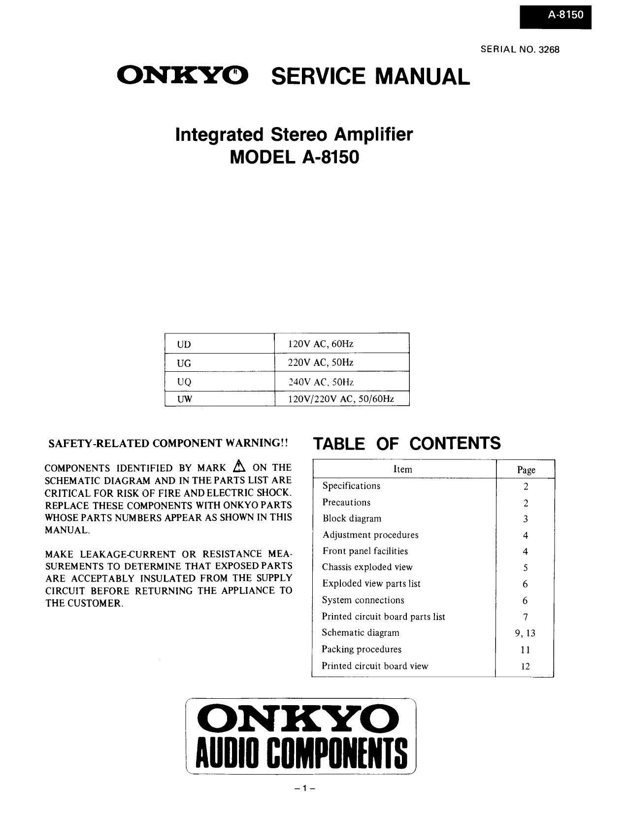
ONKYO SERVICE MANUAL
Integrated Stereo Amplifier
MODEL A-8150
UD 120V AC, 60Hz
UG 220V AC, 50Hz
UQ 240V AC. SOHZ
UW 120V/220V AC, 50/60Hz
SAFETY-RELATED COMPONENT WARNING
COMPONENTS IDENTIFIED BY MARK A ON THE
SCHEMATIC DIAGRAM AND IN THE PARTS LIST ARE
CRITICAL FOR RISK OF FIRE AND ELECTRIC SHOCKV
REPLACE THESE COMPONENTS WITH ONKYO PARTS
WHOSE PARTS NUMBERS APPEAR AS SHOWN IN THIS
MANUAL
MAKE LEAKAGE-CURRENT OR RESISTANCE MEA-
SUREMENTS TO DETERMINE THAT EXPOSED PARTS
ARE ACCEPTABLY INSULATED FROM THE SUPPLY
CIRCUIT BEFORE RETURNING THE APPLIANCE TO
THE CUSTOMER.
A-8150
SERIAL NO. 3268
TABLE OF CONTENTS
Item Page
Specifications 2
Precautions 2
Block diagram 3
Adjustment procedures 4
Front panel facilities 4
Chassis exploded view 5
Exploded View parts list 6
System connections 6
Primed circuit board parts list 7
Schematic diagram 9, 13
Packing procedures 1 1
Printed circuit board view 12
I ONKYO
I Alllllll BflMPflNENIS
-1-
Page 2
SPECIFICATIONS
Power Output:
Total Harmonic Distortion
IM Distortion
Damping Factor:
Frequency and Response:
Sensitivity and Impedance
Phono Overload:
Bass Control:
Treble Control:
Signal to Noise Ratio:
Loudness Control:
Muting:
Selective Tone Control
General
Power Su pplv:
Dimensions (W x H x D):
Weight:
PRECAUTIONS
l. Replacing the fuses
60 watts per channel, min, RMS, at
8 ohms, both channels driven from
20 Hz to 20 kHz, with no more than
0.06% THD.
0.06% at 60 watts
0.06% at 60 watts
40 at 8 ohms
15 -30,000 H2 1 1 dB
Phono (MM): 25 mV/50 kohms
Phono (MC): 350 LIV/330 ohms
Tuner/CD/AUX:150 mV/SO kohms
Tape/Play: 150 mV/SO kohms
Tape/Rec: 150 mV/4.5 kohms (phone)
150 mV RMS at 1 kHz, 0.06% THD (MM)
110 dB at 100 Hz
1:10 dB at 10,000 Hz
Phone: 83 dB (IHF A), 5 mV input
CD&Tape: 95 dB (IHF A)
+7 dB at 70 Hz/+5 dB at 10 kHz
-20 dB
:15 dB at 50 H2/16 dB at 10 kHz
European models: ACZZOV, SOHz
Canadian models: AC120V, 60Hz
British & Australian models:
AC240V, 50Hz
Worldwide models: AC12OV and 220V
switchable, 50/60 Hz
435 x 110 x 272 mm
17»1/8"x 4-5/16 x10-11/1G"
7.0 kg, 15.4 lbs.
For continued protection against risk fire, replace only with same type and same rating fuse.
CIRCUIT NO. PART NO.
F901 252050
F902 252075 or
252075CC
F911,F912 252078 or
252078CC
DESCRIPTION
SA(ST-6). Primary fuse (120V model)
25 A-SEAEAK Primary fuse (220V. 240V. HOV/220V model)
2,5A-SE-EAK Primary fuse (220V, 240V, HOV/220V model)
5A~SE7EAK, Secondary fuse (220V, 240V model)
SA-SE»EAK, Secondary fuse (220V, 240V model)
2. Insulation resistance mesurement (Only U.S.A. model)
Connect the insulating-resistance tester between the plug of power supply cable and the terminal GND on the back panel.
Specifications; More than 10 M9 at 500V.
3. Voltage selector (rear panel)
Worldwide models are equipped with a voltage selector to conform with local power supplies. Be sure to set this switch
to match the voltage of the power supply in your area before turning the power switch on. Voltage is changed by sliding
the groove in the switch with a screwdriver or similar instrument to the right or left position. Confirm that the switch has
been moved all the way to the right or left before turning the power switch on. If there is no voltage selector switch
on the unit you have purchased, it can only be used in areas where the power supply voltage is the same as that of the
unit.
EDI! CED
4 D 4
220V~ 120V~ 220V~ 120V~
at AC 120V at AC 220V