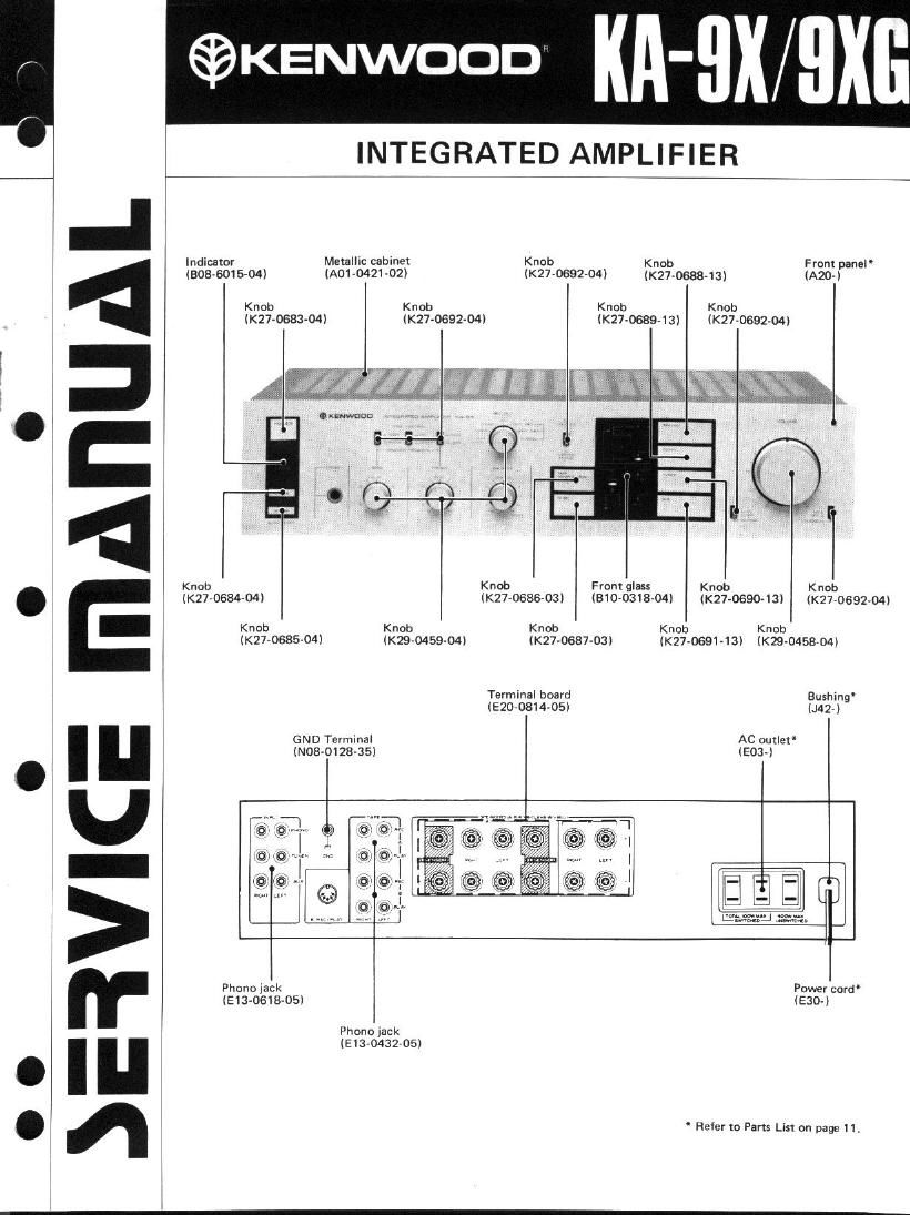
Kenwood KA 9 XG Service Manual
This is the 11 pages manual for Kenwood KA 9 XG Service Manual.
Read or download the pdf for free. If you want to contribute, please upload pdfs to audioservicemanuals.wetransfer.com.
Extracted text from Kenwood KA 9 XG Service Manual (Ocr-read)
Page 2
BLOCK &LEVEL DIAGRAM/CIRCUIT DESCRIPTION
BLOCK 81 LEVEL DIAGRAM
/- xoeaseo-io
0|~12, ICI,2
mono @- eo AMP
xiv-196040 umr ,- xtJ-asaoqo fl
su~3 vas. a
O5~B
vm 2 05,,
ss 6 0.5.23 Low FINAL 5
L 059,60 vm~4 ozs~u 5
TUNER Mm.
SUBSONIC
FILTER
AUX
r PLAY
ur:
L as:
CIRCUIT DESCRIPTION
The main amplifier employd in KA-QX (7X) consists of a
3-stage differential class A voltage amplifier and a 3-stage
Darlington class B SEPP. Unlike the conventional circuit
configuration, the final stage has a couple of circuits: one
for low voltages and one for high voltages. During normal
operation, transistors (05~08) on the 1ow-voltage side
perform their function, reducing the heat generation and
power consumption of the amplifier (Refer to "Heat
Generation and Power consumption of Amplifier" on the
next pagelt During high power output operation, transistors
(01~04) on the high-voltage side become active, ensuring
optimum operation of the amplifier with minimum heat
generation. For optimizing the amplifier operation, a
comparator circuit, holding circuit, and distributor circuit,
consisting of 029~044, are also provided.
The following explains the amplifier opearation at the
positive side of channel L (see Figure 1).
-HV
1-73V)
DRIVER
COMPARATOR
SWITCHING
"i o1~4
men FINAL
HIGH rowan you
Low POWER UPPLV
The input signal from the emitter 025 enters the distri-
butor circuit 029/033. Normally, 033 is turned on by R77
and transfers the input signal to 05 on the low-voltafe side,
If the input signal level is higher than the reference voltage
Vx (approximately 30V) of the comparator 041, 041 is
turned on through the emitter of 05 and 015. At the same
time, 037 of the holding circuit turns on, causing 029 of
the distributor circuit to turn on, When 029 turns on, the
033 base-emitter bias becomes zero, turning off 033.
Then, the input signal is transmitted to 01 on the high-
voltage side, allowing high power output operation D11
and R73 are provided to impart hystersis characteristic
(Vx->Vx', approximately 23V) to the comparator circuit
and ensure distribution operation. D15 is provided for the
comparator 041, which normally has an inverse bias. The
holding circuit (037,C27,R91 and R95i keeps 029 on for
a certain period of time (t),enabling operation of the high-
voltage side. This circuit inhibits the distributor circuit
operation if the input signal level and frequency are
substantially high, and thereby prevents the distortion
factor from deteriorating.