Kenwood DDX 8067 Service Manual
This is the 114 pages manual for Kenwood DDX 8067 Service Manual.
Read or download the pdf for free.
If you want to contribute, please mail your pdfs to info@audioservicemanuals.com.

Extracted text from Kenwood DDX 8067 Service Manual (Ocr-read)
Page 2
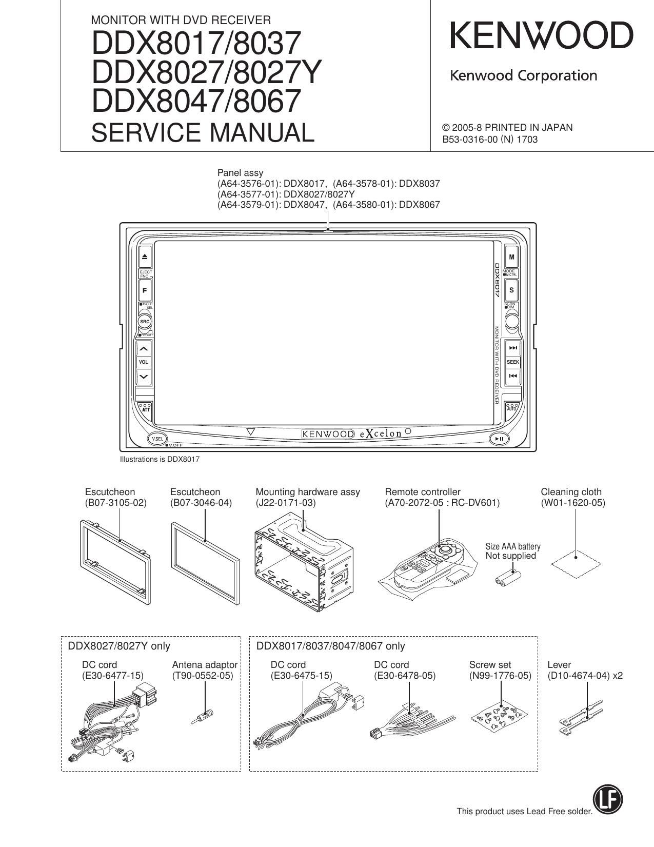
DDX8017/8027/8027Y
DDX8037/8047/8067
NOTES ON ASSEMBLING THE MECHANISM
1. Fasten Screw A so that the interval (a) will be about 5.2mm
and the interval (b) will be about 2.6mm (The interval (a)
can be measured using a pair of vernier calipers or similar
tools.)
2. Turn B so that Position (0) will come at about the center of
interval (d).
3. Then, play the test disc and fine tune A or B so that the jitter
value would be minimized.
Page 33
DDX8017/8027/8027Y
DDX8037/8047/8067
TEST MODE
0 Screen Management section
- While in the Test Mode (Including connection with special
p-com/jig), the startup will be with VIDEO screen. -> Transi»
tion to Test Mode Main screen is made with [FNC] key.
In coordination with V.SEL, AVOUT is also switched. (AVOUT
with Graphic and NAVI can be anything.)
AV|N1 - (AVIN2) - (TV) - R-CAM - NAVI-DVD (NO specific
order)
Easy Control screen can be skipped using [FNC] key.
Parking detection is ignored in Test Mode. However, Park-
ing is not ignored when Unit is special.
Reverse condition occurring in Test Mode will be made On
condition (VSEL always has ROAM). However, when Unit is
special, it will be as usual.
(When detected, Reverse will cause R-CAM interruption,
as usual.)
Default screen of System Setup will be made System 2.
Default screen of Audio Setup will be made Speaker Setup.
Default speaker selected of Speaker Setup will be made
Sub-woofer.
When VIDEO 1 video is input or at signal switching (NTSC
<-> PAL) will not be OSD displayed. (OSD display will be
made at V.SEL switching. Display will not be made at the
time ofVlDEO 1.)
O BEEP Control
- Beep will be sound regardless of destinations
(When Standby sourcing. Beep will not be sound as PWIC
limitation item.)
0 SI Control
- Default of SI will be On.
0 AVlF
' AV|N2 (AVIN1 for models with no AVIN2) Interruption will
be made default On.
- NAVI interruption SP setting will be default FRONT ALL.
. V-lN mirror mode switching will be conducted with remote
controller Tenkey [3].
- R-CAM Interruption will be made default On.
0 SCREEN Adiustment
- Default is center. With one click, FullDown <-> Center <->
FullUp.
- Default for BRT is MAX.
0 Audio
- Default for Volume is Step 30.
- Bal/Fad setting is one click: Min <-> Center <-> Max
- Default for LineMute is On.
- Xover setting is one click: Min <-> Max.
- Default for Center Speaker is Speaker is installed. (The set-
ting value is arbitrary.)
- Setting for Sub-woofer is On <-> Off. (The setting value for
On is arbitrary.)
- Default for PEQ is Flat.
- The transition for Effect Mode: Bypass+Center <-> Bypass
<-> CS ll (Music) <-> PL II (Movie) <-> Bypass+Center
OTUNER
- When E2PROM cannot be accessed, Error display will be
made. (Tuner screen)
- Forced Narrow/ Middle/ Wide switching of K3I.
By long pressing of Preset 4: Forced Narrow (***.*1MHz)
By long pressing of Preset 5: Forced Middle (***.*2MHZ)
By long pressing of Preset 6: Forced Wide (***.*3MHZ)
0 DVD
- CD media KTD-02A and DVD media, TDV-540A/TTD-100
are used.
When Test Mode is started up in with Disc and Panel Open
condition. the disc will not be ejected (The same as usual)
- Region code is set at the minute position of the time code.
At time of CDDA media, RDM key will cause transfer to Track
28.
- At time of CDDA media ,pressing TrackUP key will cause: 9
->15->10->11->12->13->14->9.
- When loading.Title1-Chapter1 (Indicated with * in table
next page)
33