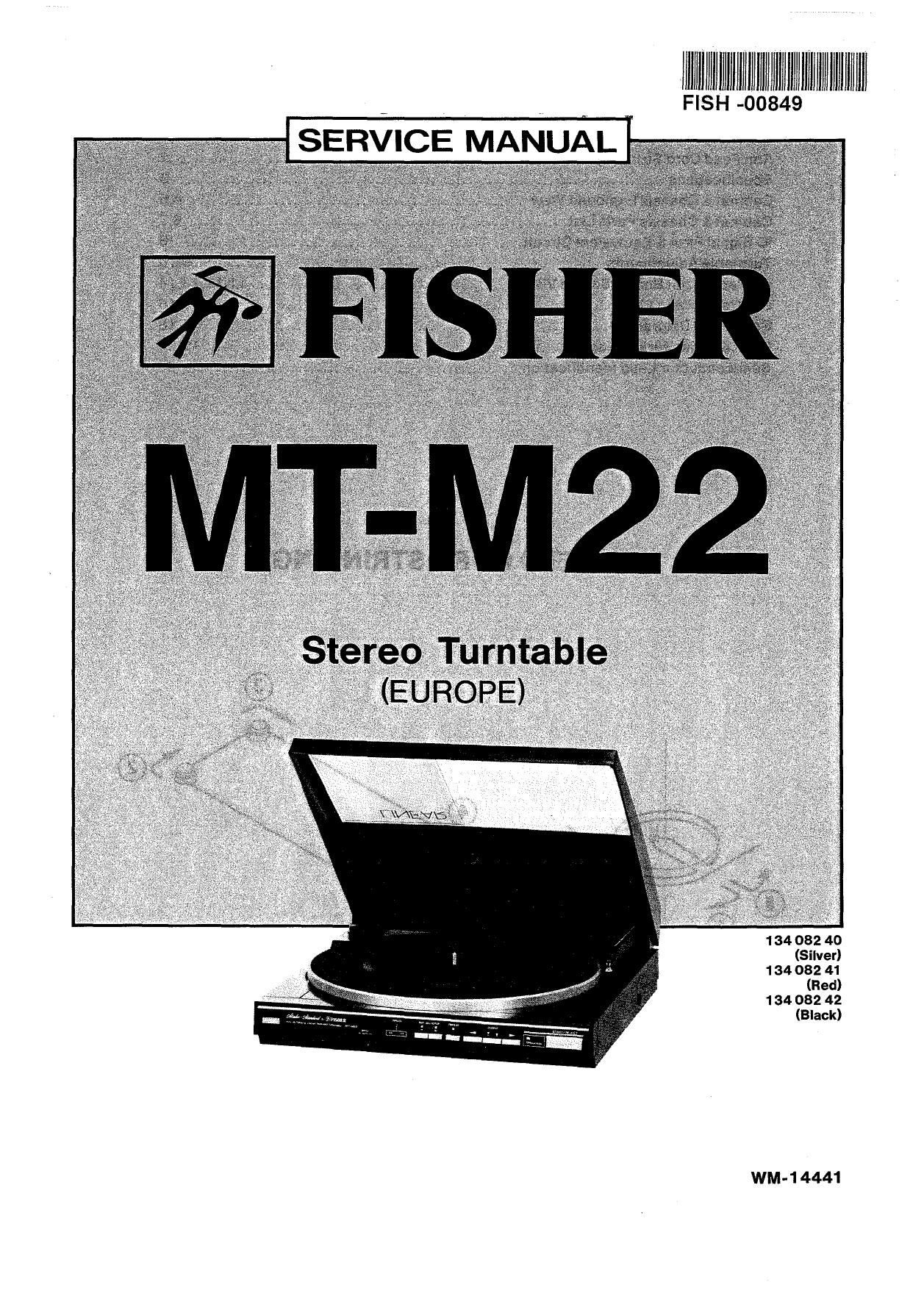
Fisher MTM 22 Service Manual
This is the 16 pages manual for Fisher MTM 22 Service Manual.
Read or download the pdf for free. If you want to contribute, please upload pdfs to audioservicemanuals.wetransfer.com.

Extracted text from Fisher MTM 22 Service Manual (Ocr-read)
Page 1
, lllllllfllilllWill}!llllllmllflllllfllllllllllllll
FISH -00849
SERVICE MNUAAL
1 34 082 40
(Silver)
1 34 082 41
(Red)
134 082 42
(Black)
WM-1 4441
Page 2
CONTENTS
Arm Feed Cord Stringing .................................................................. 2
Specifications ............................................................................. 3
Cabinet & Chassis Exploded View ..................................................... 4,5
Cabinet & Chassis Parts List ........................................................... 6,7
IC Signal Flow& EquivalentCircuit ........................................... 8
Turntable Adjustment-s .................................................................. 9,10
Printed Circuit Board (Bottom View) ......................................... 11,12,13,14
P.C.Board Parts List ............... ' ................................................... 15,16
Schematic Diagram ............... 17,18
Point to Point Wiring Diagram .......... . 19,20
Semiconductor Lead Identification ..................................................... 21
ARM FEED CORD STRINGING
Page 8
TURNTABLE ADJ USTM ENTS (Continued)
Photointerrupter Position Adjustment for Arm Feed
1 . Turn on the power switch of the unit.
2. Place a record with less eccentricity on the turntable and
play it.
3. After the record has rotated three or four times, raise the arm
by pressing theCUElNG button.
4, Turn the arm feed adjustment screw with a screwdriver
through the hole on the right side of the cabinet, so that the
arm rises straight up. (Fig. 6)
Adjustment Screw
Fig. 6
Lead-in Position Adjustment
1. Turn on the power switch of the unit.
2. Place a record on the turntable and perform the lead-in
operation.
3. Adjust the lead-in position adjustment cam, so that the
record is led into the correct position.
Note: If the cam is turned clockwise, the tonearm moves
inward. It moves outward if the cam is turned counter-
clockwise. (Fig. 7)
Lead-in Position
Adjustment Cam
Fig. 7
-10-
Page 16
FISHER
FISHER Hi-Fi Europa Vertriebs GmbH
Stahigruberring 4 Tel: 089/420 45-0
8000 Miinchen 82 Tlx: 524033
Technisches Labor/ Durchwahl -120/121
Qualiiétskontrolle
FunkstérmeBIabor ~-127/128
Service-Zentrale
Color TV -1 66
Hi-Fi/Audio -168
Video -1 72
Auioradio -170
Ersatzteiilager -155/156
Techn. Schulung -174
Weitere Service-Zentralen in BRD (keine Ersatzteilbestellungen)
Oiienbach/ Frankfurter StraBe 121 Tel: 069/88 30 45/48 Hamburg Spaidingstra0e1 Tel: 040/23 12 23/ 24
Frankfurt 6050 Offenbach Tlx: 412 558 2000 Hamburg Tix: 2 1 73 839
Military Frankfurter SlraBe 121 Tel: 069/88 80 45/48 Ditzlngen Max-Eyih-Straee 1 1 Tel: 07 1 56/50 88
6050 Offenbach Tlx: 412 558 7257 Diuingen Tlx: 7 245 278
Dflsseldorf-Erkrath Alben-Einstein-Strafle 8 Tel: 021 1/200 05-0 Berlin Drewliz 25 Kaulbach Tel: 030/751 20 01
4006 Erkralh 1 Tlx: 8 588 563 (Fisher Eisenacher Strafle 53 Tix: 1 86 460
Vertragswerkslan) 1 000 Berlin 62
Unser FISHER-Team stem lhnen jederzeik game zur Verffigung Ersatzleilbesleliungen wickeln Sie lame ausschlieslich mi: unserer Service-lemme
MiJnchen ab.
Senden Sie uns im Garantiefall die ausgeiiiilte Gamniiekarte ein. Bei unverkaufien Lagemerfimn des Fachhandeis gilt ais Garantienachweis elns
eidessiamiche Versicherung mil eingelragener Modellbezeichnung und Gerfite-Nummar oder eln Liefemachweis. Die gleiche Regeiung besleht auch iiir
Reparaturaufirége.
Bitta gaben Sie unbedingtdie Ersatzieil-Nummer und die Modellbazeichnung an.
Sie sparen so wertvoile Zeit. Vielen Dank March/85/2,000 Printed In Japan