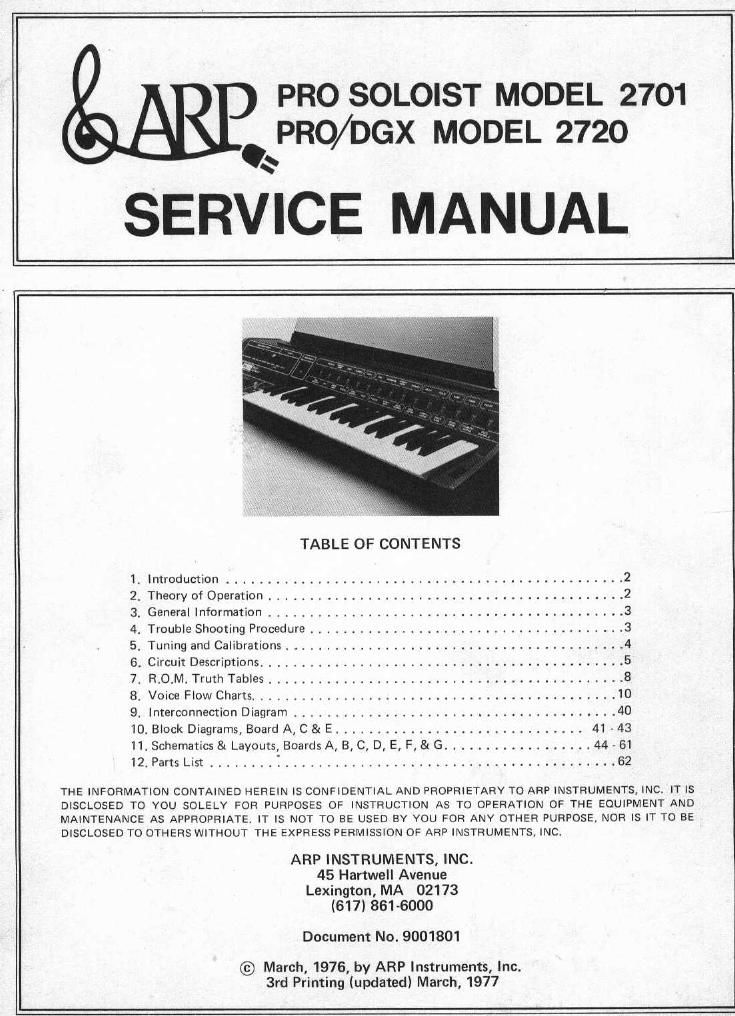
Arp pro soloist pro dgx service manual
This is the 64 pages manual for arp pro soloist pro dgx service manual.
Read or download the pdf for free. If you want to contribute, please upload pdfs to audioservicemanuals.wetransfer.com.
Extracted text from arp pro soloist pro dgx service manual (Ocr-read)
Page 1
PRO SOLOIST MODEL 2701
PRO/DGX MODEL 2720
SERVICE MANUAL
TABLE OF CONTENTS
1. Introduction ................................................ 2
2. Theory of Operation ........................................... 2
3. General Information ........................................... 3
4. Trouble Shooting Procedure ...................................... 3
5. Tuning and Calibration: ......................................... 4
6. Circuit Dascriptions ............................................ 5
7. ROM. Truth Tables ........................................... 8
8. Voice Flow Charts ............................................ 10
9.1nterconnection Diagram ....................................... 40
10. Block Diagrams, Board A, C 81 E .............................. 41 43
11. Schematics 8: Layouts, Boards A, B, C, D, E, F, & G .................. 44 51
12. Parts List ........ i ........................................ 62
THE INFORMATION CONTAINED HEREIN IS CONFIDENTIAL AND PROPRIETARY TO ARP INSTRUMENTS, INC, IT IS
DISCLOSED TO YOU SOLELY FOR PURPOSES OF INSTRUCTION AS TO OPERATION OF THE EQUIPMENT AND
MAINTENANCE AS APPROPRIATE. IT IS NOT TO BE USED BY YOU FOR ANY OTHER PURPOSE, NOR IS IT TO BE
DISCLOSED TO OTHERS WITHOUT THE EXPRESS PERMISSION OF ARP INSTRUMENTS, INC,
ARP INSTRUMENTS, INC.
45 Hartwell Avenue
Lexington, MA 02173
(617) 861-6000
Document No. 9001801
© March, 1976, by ARP Instruments, Inc.
3rd Printing (updated) March, 1977
Page 2
1. Introduction
Included in _this service manual are troubleshooting
references which if used properly can greatly reduce
the repair time of the Pro Soloist.
Section 2 covers the signal flow through the Pro
Soloist. Section 3 describes design techniques unique
to the product. Section 4 describes 'where to start'
when a problem occurs. The circuit descriptions in
section 5 should be consulted once a faulty circuit
has been identified by the use of the R.O.M. truth
tables and Voice Flow charts in sections 73nd 8.
VOICES AND EFFECTS
CONTROLS:
Porramenta- Enables the pitch to slide from note to
note.
Panama/ltd Speed-Regulates the time required to
slide from note to note.
Touch Sensitivity-Controls the over-all amount of
keyboard touch sensor effects.
Brilliance-Permits the addition or subtraction of
Bassoon Buzz Bassoon brilliance.
English Horn Sax
Shoe Space Reed Volume- Regulates the overall volume of the
lam Tamar _ instrument.
Flute Song Whistle
Tuba Noze
Trombone Pulsar Repeat-Creates the rapid pick strokes of string
French Horn Comic Wow instruments.
Trumpet Mute Trumpet
3?? Steel 9" Vibrato/Repeat Speed-Controls the vibrato speed and
rolln Harpsichord repeat rate.
Bass Space Bass
Piano Steel Drum
Banio Country Guitar Octave Transpose Switch-Transposes the instrument
Fuzz Guitar I Fuzz Guitar II P 3"" dOW" 0"? 013-
2. Theory of Operation Waveform Generator board. A sawtooth wave and a
The Pro Soloist is a hybrid of digital and analog cir~
cuits. The internal flow of the audio signals is, in
most respects, quite similar to any of our other
synthesizers. That is, a raw signal (pulse or sawtooth
wave) is processed through a voltage controlled filter
and a voltage controlled amplifier to the output of
the instrument. Two envelope generators (ADSR and
AR) are available to control the VCF and VGA to
determine the attack and decay characteristics of the
instrument. In addition to the voltage controlled
filter, there are fixed band pass filters which shape
the raw waveforms for particular voices.
In variable synthesizers, such as the ARP Odyssey or
the ARP 2600, the signal paths, oscillator waveforms
and filter characteristics are adjusted manually, In the
Pro Soloist, each of these settings are programmed by
a digital memory. (Read Only Memory, or R.O.M.).
Referring to the block diagram, Board A is the
pulse wave are supplied(at the correct pitch) to Board
C, the Filter board. Board C contains the voltage
controlled filter (VCF), the voltage controlled ampli-
fier (VGA), and 14 fixed filters. The signal paths
through board C are determined by the R.O.M. out-
puts which select one of several paths through the
different filters.
Board B provides the ADSR or AR output to the
VCF and/or the VGA (again determined by the
R.O.M.s). Board E (keyboard electronics) sends a 6
bit (6 line) code to board A to control the pitch of
the oscillator. Board E also supplies the envelope
generators on board B with a gate and trigger. Board
F, the Voice Selection board, generates a 5 bit code
which addresses all of the R.O.Ms (eight total) which
in turn program the signal paths and filter settings.
The Special Effects board (D) generates the touch
sensor effects: vibrato, growl, wow, volume, brilliance
and pitch bend.